
Aluminum miter angles need an identified reference, view and end orientation. A number such as 45° does not completely define a cut-list row. Show the dimensioned lines or faces, identify the part’s ends, retain the angle tolerance and confirm how the drawing requirement maps to the supplier’s machine convention.
This guide addresses five communication errors in drawings and purchase reviews. Its geometry examples are not machine settings or measured cutting results.
A clear angle record includes
- The drawing view and the two features that define the angle.
- The identity and orientation of each end of the part.
- The controlling units, tolerance and approved inspection reference.
On this page
1. Leaving aluminum miter angles without a reference
Write the angle beside the features that define it. Identify the relevant drawing view and show the dimension arc. “Cut at 30°” leaves the reader to decide what the 30° is measured from.
For an ideal two-dimensional example, let a cut line make an acute angle of 30° with a profile’s longitudinal axis. The acute angle to a line perpendicular to that axis is 60°. These are two descriptions using different references; they do not represent two unrelated cuts.
The example explains why the reference matters. It does not prescribe what a saw’s angle display should show. The machine’s convention still needs to be mapped to the approved drawing by the responsible supplier.
Autodesk’s angular-dimension documentation describes angles defined by lines or points and explains that the chosen quadrant affects the dimensioned angle. That is a useful drawing-review principle: the dimension arc needs to identify which angle is intended. A CAD dimension does not by itself define a saw controller’s input.
Clearer record: identify the reference line, cut line, drawing view and intended angle arc, then retain the specified angle tolerance. Keep the drawing number and revision with the record.
2. Using left and right without naming the view
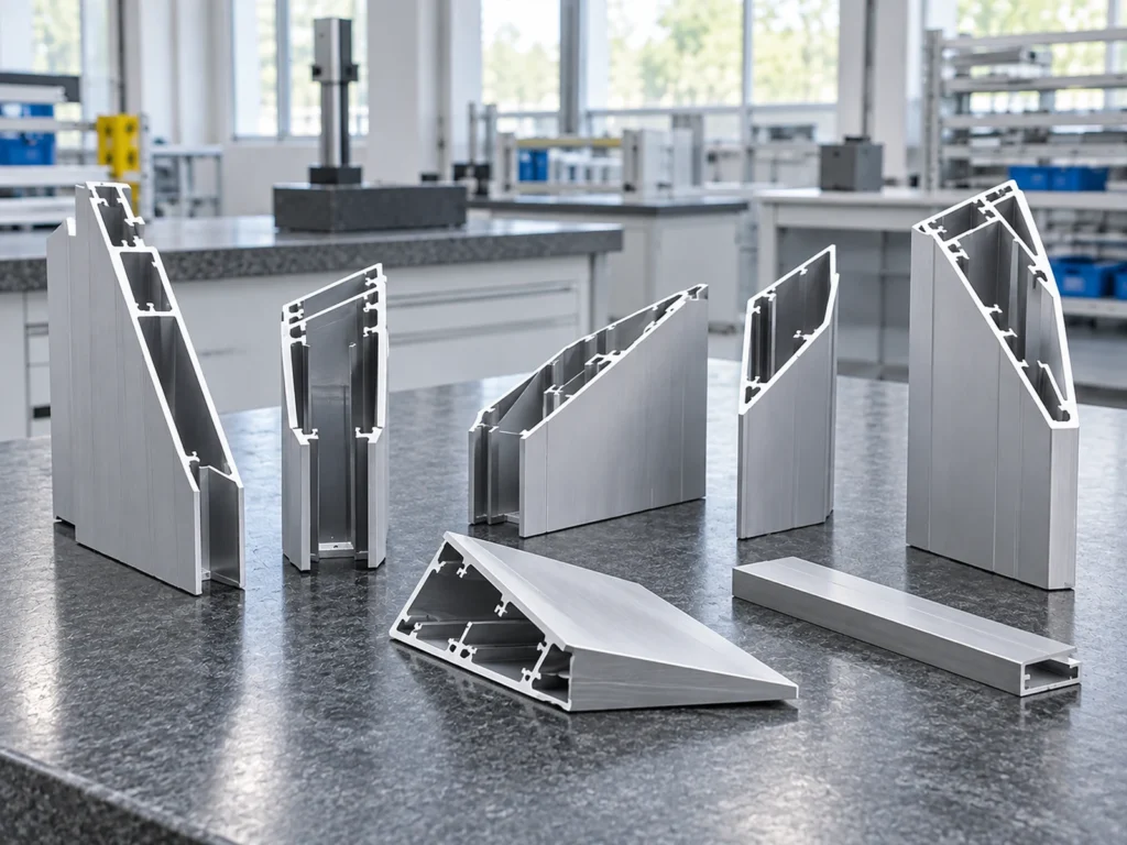
Left and right can change when a part is viewed from its other side or turned end for end. A cut list should preserve the actual part orientation instead of relying on an unstated viewing position.
Name the part’s end A and end B. Identify a reference face or other unmistakable feature, and show the cutting requirements in the same drawing view. Use the approved drawing’s identification rather than inventing a new orientation for production.
For a section with a groove or asymmetric wall arrangement, include that feature in the review view. Two pieces with equal overall length can still belong to different identities when their ends or reference faces are mirrored.
Clearer record: keep a labeled view for each handed part. Give each part its own identity, quantities and end requirements. If the machine supplier proposes a loading orientation, have it checked against those identified features.
Our angle-section drawing guide discusses why the legs and faces of an L section need clear identification. Our cut-list revision guide helps keep an updated orientation connected to the correct job.
3. Copying an assembly angle into an end-angle field
An assembled corner angle and a member’s end angle describe different features. Keep the assembly drawing and component drawing connected, but do not assume their numerical angle values should match.
In an ideal planar corner, the meeting members and joint geometry determine how the end faces relate to the assembly. Real drawings may also include unequal members, offsets, different reference edges or another joint design. Use the actual component requirements rather than a familiar corner shortcut.
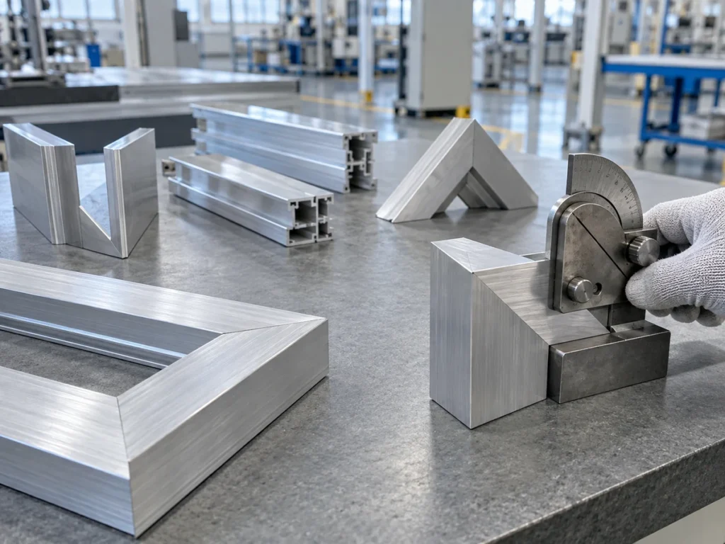
A square-looking assembled corner does not establish the individual end angles. A photograph also cannot supply the controlling dimensions, fit requirements or measurement results.
Clearer record: identify the assembly angle separately, then list the end requirements for each component. Keep the length reference with each component because a long-point and a short-point length are different dimensions.
Our miter-length calculation guide covers the length-reference question. Changing or clarifying the end angle should not silently change the dimensioned edge.
4. Treating decimal degrees as degrees and minutes
Keep the angle notation intact when preparing a list or quotation. Decimal degrees and degrees with angular minutes are different ways to express an angle. Their digits are not directly interchangeable.
NIST’s plane-angle unit table defines an angular minute as one sixtieth of a degree. An angular second is one sixtieth of an angular minute. These angle units should also remain distinct from units of time.
A fictional dimension of 30° 30′ equals 30.5°. It does not equal 30.30°. Likewise, 30° 5′ equals 30 + 5/60 degrees, or approximately 30.083333°. These are conversion examples, not recommended angle targets.
Keep the original dimension and tolerance in the source record. If the receiving system requires decimal degrees, have the conversion and required rounding reviewed. Extra decimal places do not establish the machine’s angular accuracy.
Clearer record: identify the original notation, approved equivalent and the format required by the actual input workflow. Do not rely on a plain text field to interpret symbols or separators automatically.
Our inch-to-millimeter guide addresses length units. An inch-to-millimeter factor does not apply to angle values, and changing a length unit does not change the angle’s geometry.
5. Treating machine movement range as the finished-part requirement
A machine quotation may describe pivoting, tilting, inward or outward movement. Those terms belong to the machine’s documented axes and conventions. The drawing instead describes the geometry required on the actual part.
Elumatec’s DG 104 technical page lists pivoting and tilting ranges separately and refers cutting capacity to a cutting diagram. This shows why an angle range needs its movement context. These are descriptions of that supplier’s equipment, not verified functions or ranges for a JiurunCut model.
Ask the supplier to review the actual section at the required end geometry. A permitted movement range alone does not prove that the profile fits the cutting envelope at every angle or that all required faces can be supported and held in the ordered arrangement.
Keep compound requirements explicit. A part requiring two geometric orientations cannot be defined by one unlabeled planar angle. Obtain the relevant views and supplier confirmation for the complete part.
Clearer record: retain the component drawing as the requirement, then ask the supplier to document the proposed machine arrangement and any remaining review items. Use the approved machine documentation for operation.
A short review before the cut list is released
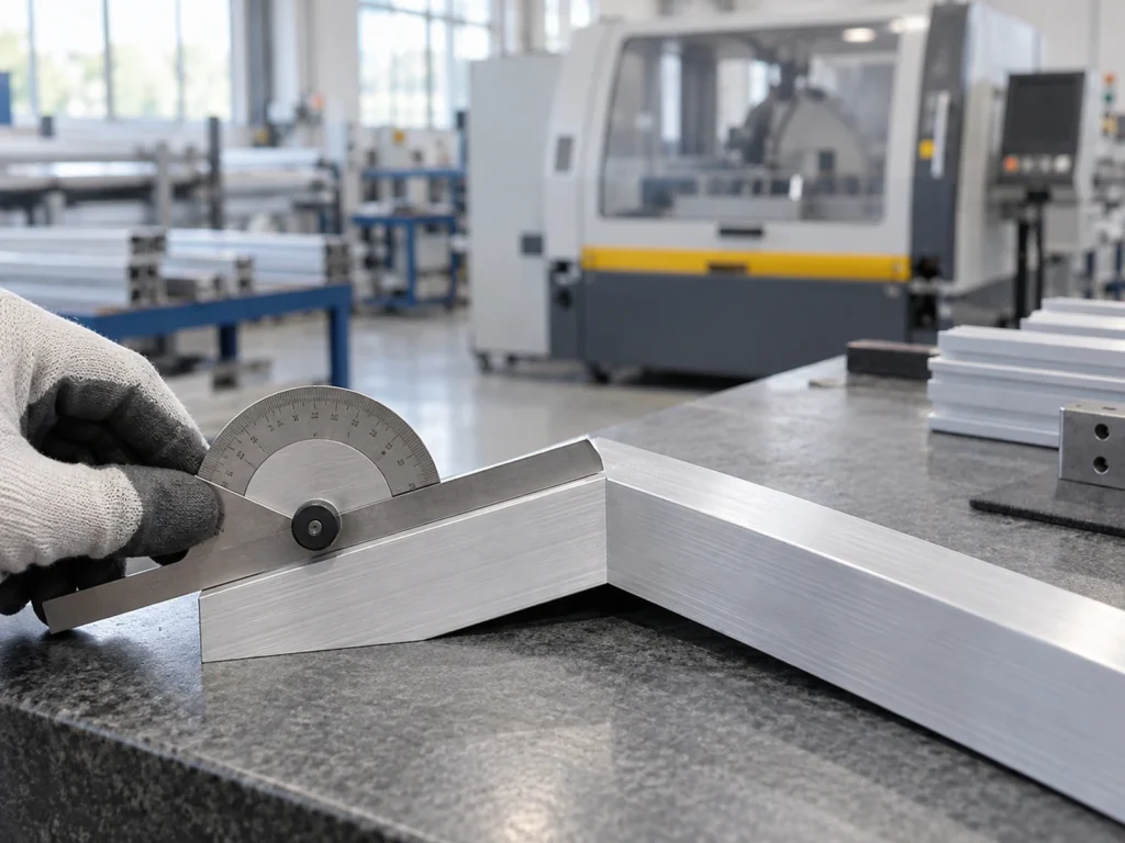
Read one representative part from drawing to finished-part record. Check the controlling revision, reference face, end identities, length endpoints, angle references, notation and tolerances.
Repeat the review for a mirrored or compound part if the job includes one. A review of a simple square-cut member does not resolve the different geometry of an angled member.
Keep open questions visible and assigned to an owner. When a drawing reference is clarified, retain the approval and update the affected records through the agreed revision process.
For a machine proposal, send JiurunCut the section and component drawings, end requirements and planned quantities. Request a review of your miter-cutting task with the quotation.
Common angle-record questions
Can 30° and 60° describe the same end line?
Yes, in the ideal example above they use perpendicular references. Identify the reference lines before deciding whether two angle statements conflict.
Does a left-hand part become a right-hand part when turned around?
The view may change, but the approved part identity and features remain the requirements. Use labeled ends and a reference face to prevent viewing direction from redefining the part.
Is a stated machine angle range an accuracy guarantee?
No. Movement range, part geometry, cutting capacity and verified angular performance are separate items in the purchase review.