
Aluminum cut part deburring removes unwanted burrs, while a defined chamfer specifies an edge geometry that must be produced and checked. A request to remove burrs does not automatically specify a chamfer size, angle or radius. Define the required edge condition on the drawing before comparing cutting and finishing proposals.
Start with the edge’s function and the delivery state. Identify which edges need treatment, which dimensions must remain protected and who supplies any operation after sawing. This gives the supplier a concrete requirement to review.
A clear edge requirement answers three questions
- Which physical edges are covered?
- What condition or geometry is required?
- At what production stage is it checked?
On this page
Three aluminum cut part deburring requirements to clarify
These terms are related, but a purchasing brief should explain the intended result. Suppliers may use short finishing descriptions differently. Ask what the proposal means for the particular edges on your part.
| Requirement | Clarification needed |
|---|---|
| Remove burrs | Identify covered edges and the agreed acceptable condition. |
| Break an edge | Define permitted edge change and any limits that apply. |
| Produce a defined chamfer | Identify size, angle, applicable tolerances and inspection basis. |
A general finishing note can describe an edge condition without fully defining a geometric feature. If a mating part requires a particular chamfer, retain that geometry as a drawing requirement rather than leaving it to an informal interpretation.
The public ISO 13715:2017 overview distinguishes undefined-edge indication from geometrically defined edges, which it directs to general dimensioning principles. This scope distinction supports clear drawing language; the overview alone is not a complete drafting or inspection procedure.
Protolabs’ CNC finishing page describes deburred edges with visible tool marks and separate finish choices. That manufacturer example shows why an edge treatment and an overall surface appearance should both be specified. It establishes no standard finish for JiurunCut.
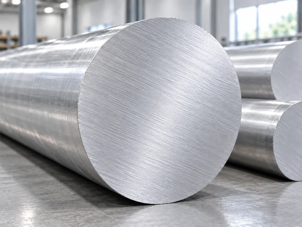
Identify the edges before choosing a process
Mark the cut ends and relevant perimeter edges on the drawing. A hollow section may have outside and inside boundaries at each end. A multi-chamber extrusion can introduce additional internal edges that are not described by a note about the outer corner.
Keep cut edges separate from existing longitudinal profile features. The treatment requested for a newly sawn end may differ from the treatment allowed on a visible finished surface. Make that boundary explicit.
Where only selected edges require a defined geometry, identify them individually. Avoid relying on a photograph without dimensions to distinguish the important locations. A supplier needs to connect the request to an identifiable drawing feature.
If an internal edge is difficult to access, raise that question during the process review. Confirm whether the proposed operation can address the specified location without changing other features. This guide does not prescribe a deburring tool or operating method.
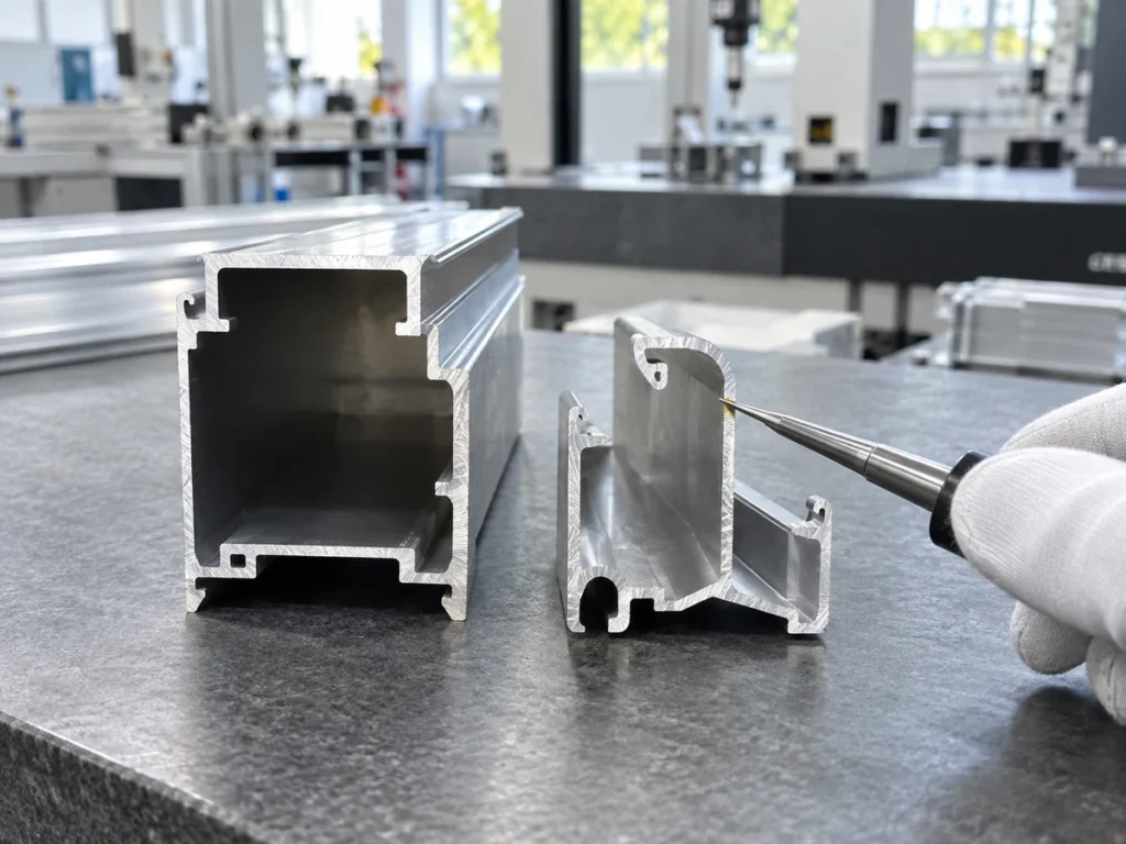
Protect the dimensions and surfaces that matter
State which surfaces define finished length, fit or other functional dimensions. Edge treatment changes material at the edge. The drawing should let the supplier understand which geometry may change and which requirement remains controlling.
A radius and a chamfer are different shapes. If either is functionally acceptable, have the drawing owner define that flexibility. If only one geometry is permitted, keep the requirement specific.
On a thin wall, review the proposed treatment relative to the actual section. Do not transfer a chamfer from a thick solid part onto a thin extrusion without a drawing review. A general note needs to be interpreted within the part geometry.
Visible surfaces can also matter after edge treatment. Identify the areas where handling or processing marks are limited and agree on the relevant appearance criteria. The anodized-profile guide explains why an incoming finish and a newly exposed cut end need separate review.
For length and angle requirements, retain the correct measurement references. The finished-length datum guide helps keep those definitions visible through the cutting and finishing stages.
Write the finishing handoff into the production scope
Define the state delivered by the saw operation. Is the next process expecting an as-cut blank, an edge-treated blank or a fully finished component? These are different delivery boundaries even when the main cutting dimensions are identical.
Assign any secondary operation to a named process or supplier. Keep equipment capability questions separate from a requirement for the finished part. A saw quotation does not establish that a separate chamfering operation is included.
Describe the inspection stage relative to secondary processing. If the handoff requires a treated edge, an earlier as-cut inspection cannot establish that later condition. Record the sample’s production state beside its results.
Review the workload for the complete handoff. Transport, sorting, finishing and inspection may remain outside the visible saw cycle. The accepted-part cost guide helps compare proposals using the same delivery requirement.
An invented tube example makes the scope difference visible
Consider two hypothetical rectangular tube parts. Both have a nominal cut length of 500 mm. Part A calls for burr removal on identified cut-end edges, with the acceptable edge condition defined in its drawing. Part B additionally requires a specified external chamfer.
For Part B, assume the drawing owner has defined a 0.5 mm chamfer at 45° on the identified outside edges, with the relevant tolerances specified elsewhere in the drawing. This number is a teaching example, not a recommended size for an actual tube wall.
The same nominal length does not make the finishing scope identical. Part B needs review of the defined geometry, the wall section, the process that produces it and the corresponding inspection. Part A’s deburring description does not establish Part B’s chamfer.
These are invented drawing scenarios. They provide no JiurunCut machine feature, finishing capacity or measured result. The appropriate edge requirement comes from the actual design and application.
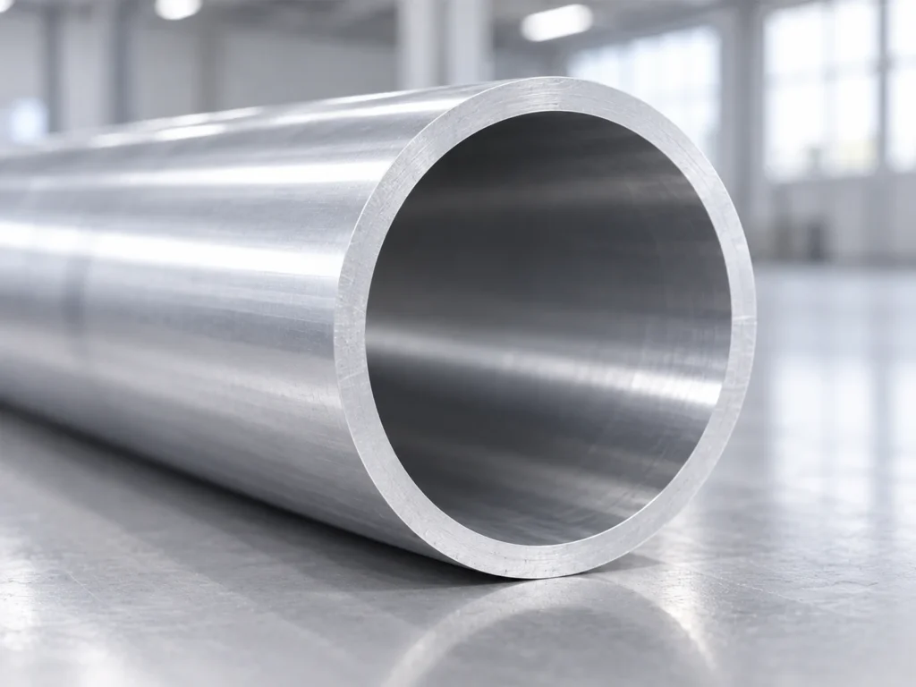
Agree on inspection before treating a sample as approved
Connect each edge requirement to the planned review method. Retain the drawing revision, feature location and sample identity. Distinguish a visible appearance check from a dimensional check of a defined chamfer.
Agree how ambiguous edges or missing drawing details are handled. Raise the issue with the drawing owner rather than creating an informal limit during the supplier demonstration. Keep unresolved questions visible in the trial record.
A representative sample can support discussion, but its approval scope should be stated. Identify which edge requirements were actually checked and which remain open. The acceptance checklist helps record that distinction.
Send JiurunCut the section drawing, cut-end details and required delivery state to discuss the cutting scope. Include secondary finishing requirements so the proposed handoff can be reviewed against the actual part.
Common questions
Does burr-free mean a specific chamfer?
No. A statement about burr condition does not define chamfer size and angle. Retain the required geometry and applicable tolerances in the drawing.
Can I specify the same edge treatment on every profile?
Review each section’s functional surfaces, wall geometry and access. The appropriate requirement must fit the actual part rather than an assumed universal edge size.
Is a smooth-looking photograph enough to approve deburring?
No. It may illustrate an appearance, but it does not establish the agreed edge condition or dimensional result. Use the defined inspection basis and identified sample.
Should aluminum cut part deburring be included in a machine trial?
Include the relevant delivery requirement. Clarify whether the trial evaluates an as-cut blank, a secondary finishing operation or the complete handoff, and record exactly what was checked.