
HVAC aluminum frame cutting should deliver identified members that fit the intended joints and arrive as complete assembly kits. Start with the frame drawing, then define each cut member, its end condition and its inspection method. A successful saw trial should include the handoff to assembly.
Three things to remember
- Frame dimensions and individual cut lengths are different drawing inputs.
- Review the connection, panel interface and visible faces together.
- Release a complete identified kit, with any unchecked features clearly recorded.
On this page
1. What belongs in the HVAC aluminum frame cutting list?
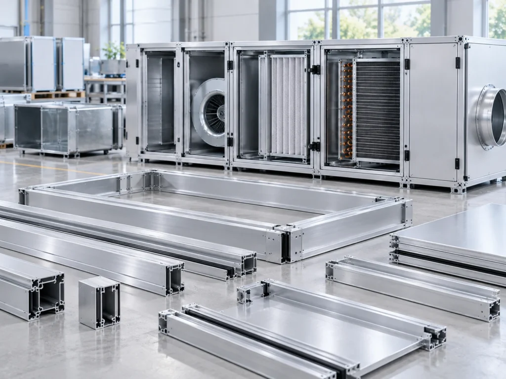
List the actual saw-cut members, rather than using the equipment name as the part description. An enclosure can contain rails, posts, cross-members and separate brackets. Some components may be purchased finished or made by another process. Mark the scope so the saw quotation covers the right work.
Hydro describes aluminum use across heating, ventilation and cooling equipment, including housings and ventilation applications. That establishes the wider application context. Your assembly drawing must still define the particular frame sections, connections and acceptance requirements.
Give every member a part ID and profile reference. Show its role on the assembly drawing: top rail, lower rail, upright or internal support. If two similar members have different holes, ends or orientations, keep them as separate parts even when their saw-cut lengths match.
This helps both the supplier and the assembly team. A drawing number explains what the member should become. A kit number explains where it belongs after cutting. Use both, and retain the drawing revision through every handoff.
2. Which drawing defines the joint and the cut end?
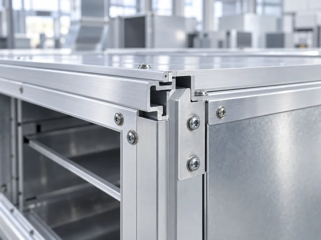
The outside frame size does not automatically equal the required member length. A member may fit between posts, overlap another rail or enter a connector. Let the design drawing define those relationships. Do not subtract a generic allowance simply because another frame uses it.
For each part, identify the finished length datum, cut angle and orientation. Show any end condition that matters at the joint. State whether the saw delivers a blank for later machining or a member ready for assembly. Drilled holes and threaded features need their own process scope.
Keep panel interfaces visible in the review. A rail can satisfy an isolated length measurement while the assembled frame still prevents the specified panel from fitting. Ask the designer which dimensions control that interface and which checks belong to assembly.
- Finished-member drawing with units and revision
- Connection drawing or an approved assembly detail
- Visible faces and surfaces that must remain acceptable
- Features completed after sawing, with their process owner
For more detail on reference points, use the finished length datum guide. Keep the selected measurement method consistent during the sample trial and later production checks.
3. What should the first trial frame prove?
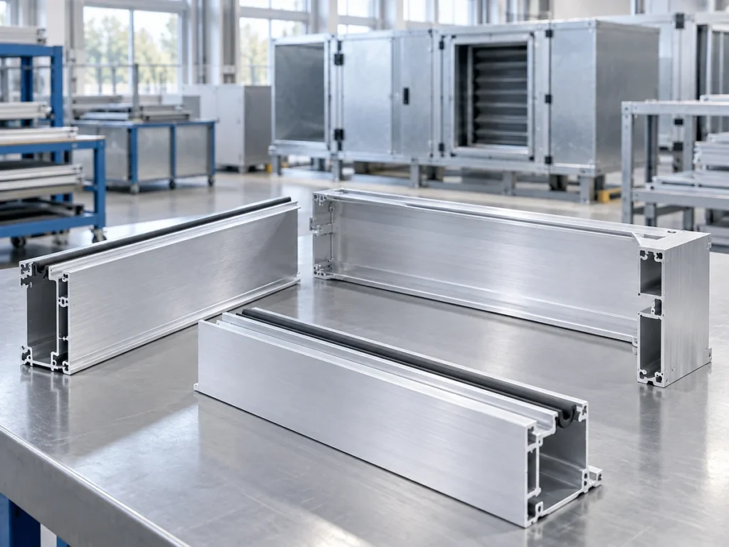
Select a representative joint and frame arrangement before running a large batch. Include the member shapes and interfaces that influence equipment selection. Check both the measured parts and how they fit together. Record any adjustment made between those two stages.
Review the supports and clamp contact points against each section. Explain where a fixture may touch and where a finish or functional surface requires protection. The supplier should identify the proposed configuration and demonstrate it with representative material.
After cutting, inspect the members through normal removal and handling. Record length, agreed end checks, visible damage and identification. Then assemble the chosen sample using the approved connections. Keep results linked to the actual drawing revision.
Separate the conclusions. A member-length result, a joint-fit result and a panel-fit result answer different questions. None of those measurements alone establishes air leakage, thermal behavior, acoustic performance or the complete HVAC unit’s compliance. Those require the applicable system validation.
4. How can mixed frame sizes reach assembly as complete kits?
Use a kit list that follows the approved bill of materials. Identify each part before similar-looking members are mixed. Keep accepted pieces separate from parts awaiting review. A complete-looking stack can still contain the wrong revision or a missing mirrored member.
Invented planning example: two identical rectangular frames each require four A rails, four B rails and four C posts. The following quantities describe this example only. The chosen lengths are finished-member drawing inputs; they are not dimensions inferred from a real HVAC unit.
| Member | Quantity to deliver |
|---|---|
| A rail — 800 mm | 4 per kit; 8 total |
| B rail — 600 mm | 4 per kit; 8 total |
| C post — 1,000 mm | 4 per kit; 8 total |
The order therefore needs 24 accepted members. Cut setup pieces and rejected parts do not count toward that requirement. Record them separately when planning starting stock and trial material. The cutting list guide covers the wider stock-planning inputs.
If one A rail remains unaccepted, mark the affected kit as incomplete. Do not silently substitute a different length or drawing revision. The record should let assembly see the shortage immediately and let the cutting team replace the correct member.
5. What should the cutting team hand over?
Keep the release record short enough to use at the work area. It should identify the kit, drawing revision, accepted quantities and unresolved issues. Name the next operation or assembly destination. Include any surface or end feature that still needs checking.
Record the material and section, the fixture used, the approved cutting setup and the first-piece result. For a mixed order, show where one part identity changes to another. A program name alone cannot explain which drawing or orientation was followed.
Agree how members will be separated and supported during transfer. Check that the chosen handling method keeps the parts identified and protects the required surfaces. Packaging needs to suit the actual member shape and finish; a photograph of a completed frame does not specify that method.
Finish the trial report with three simple headings: accepted, needs adjustment and not tested. Use it to decide whether the quotation needs a fixture change, a different collection arrangement or an additional process. This makes the next supplier discussion specific and useful.
Common questions
Can I send only the outside frame dimensions?
They help explain the assembly, but the saw review needs finished-member drawings and joint details. Connection geometry can change the required cut length.
Does a good frame fit validate the HVAC unit?
No. It supports the stated component and assembly checks. System performance and compliance require their own tests and acceptance criteria.
Can a saw trial include later drilled features?
Only when that operation is part of the agreed trial scope. Identify what the saw supplies, who completes the remaining features and when the final member is inspected.
What is the simplest way to avoid missing members?
Use a kit list with accepted quantities by part ID. Keep incomplete kits marked and record rejected or unchecked pieces separately from delivered quantities.
Discuss your HVAC aluminum frame cutting project
Send a profile section, a finished-member drawing and one representative assembly detail. Add your kit quantities and explain how members reach assembly. JiurunCut can review the cutting scope and discuss a suitable machine direction and sample plan.