
T-slot aluminum cutting starts with the assembly drawing, not just the outside dimensions of the finished frame. Identify each member’s finished length, profile reference and connection details. Then separate saw cutting from any drilling, tapping or other preparation required by the selected connector.
A clear cut list gives the cutting cell a defined part to make. A clear assembly drawing gives the next operation a defined frame to build. Both need to describe the same revision.
Find your question
Which profile belongs in the T-slot aluminum cutting job?
Use the profile supplier’s part reference and cross-section drawing. Outside width and height alone may not describe the slot arrangement, center features or connector interface you need.
Keep the profile reference on both the bill of materials and the cut job. Include the specified material and finish where they matter to the project. If an order allows substitutions, have the design owner approve the exact replacement.
Do not select a connector from a similar-looking photograph. Match it to the supplier’s profile series and connection documentation. Metric and inch-based systems can also need different hardware and job data.
- Profile: exact supplier reference and cross-section.
- Part: member ID, drawing revision and required quantity.
- Interfaces: connectors, panels or accessories that use the member.
- Condition: material and finish required by the approved specification.
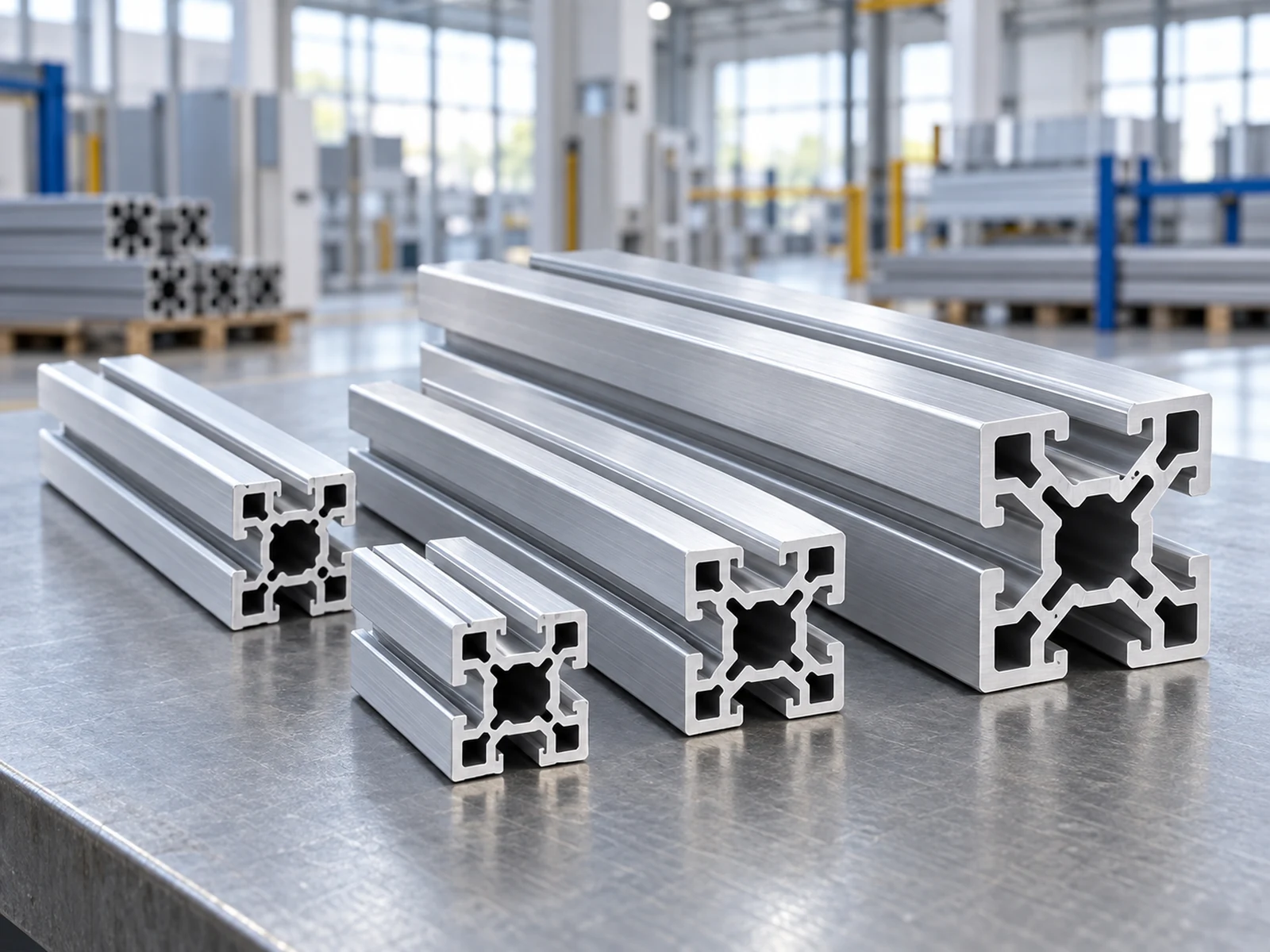
Which length goes on the cut list?
The overall frame dimension and the individual member length can be different. Review how the members meet: some may run across the full assembly, while others fit between adjacent members.
Use a dimensioned part drawing or an approved member schedule. The cutting operator should not have to infer finished lengths from an unannotated 3D view.
A simple length example
The following dimensions are invented to explain the geometry. Imagine an assembly that is 600 mm wide overall. Two side members each occupy 40 mm of that width. One crossmember fits directly between their inside faces, with no specified gap or connector offset.
For that particular arrangement, the crossmember length is 600 − 40 − 40 = 520 mm. Cutting it at 600 mm would not produce the described assembly.
This is a calculation example, not a general allowance for T-slot frames. If your joint includes a gap, offset, plate or different member arrangement, use the approved drawing to determine the length.
| Drawing item | Illustrative value |
|---|---|
| Overall assembly width | 600 mm |
| Width occupied by two side members | 80 mm |
| Crossmember between the inside faces | 520 mm |
Also define how finished length is measured. Straight-cut and mitered members need clear reference points. For a mitered part, a long point, short point and centerline are different references.
The finished-length datum guide explains how to make that reference consistent between the drawing and inspection.
Is saw cutting enough for the selected connector?
Some frame connections use the existing profile slots. Other connections need additional end or cross machining. The answer depends on the exact connector, not on the fact that the profile has T-slots.
For example, 80/20’s standard end fastener 20-3895 requires an end tap on one profile and an access hole in the mating profile. That is a specific connector requirement; it should not be applied automatically to every T-slot system.
A broader 80/20 fastening-method overview distinguishes connections that need profile machining from external options that use the slots. Check the instructions for your chosen hardware before issuing the part drawings.
Define the handoff between cutting and machining
Write down what each operation delivers. If the saw cell supplies cut blanks for another machine, show any required allowance on the controlled drawing. If parts are delivered ready for assembly, list the additional preparation and who performs it.
A CNC saw feeding sequence should not be assumed to drill or tap connector features. Confirm the equipment scope in the proposal. Keeping these operations separate in the job plan makes quotations easier to compare.
- Which ends need preparation?
- Which faces carry access holes or other features?
- Does the cut part need an allowance for a later operation?
- Who checks the finished connector interface?
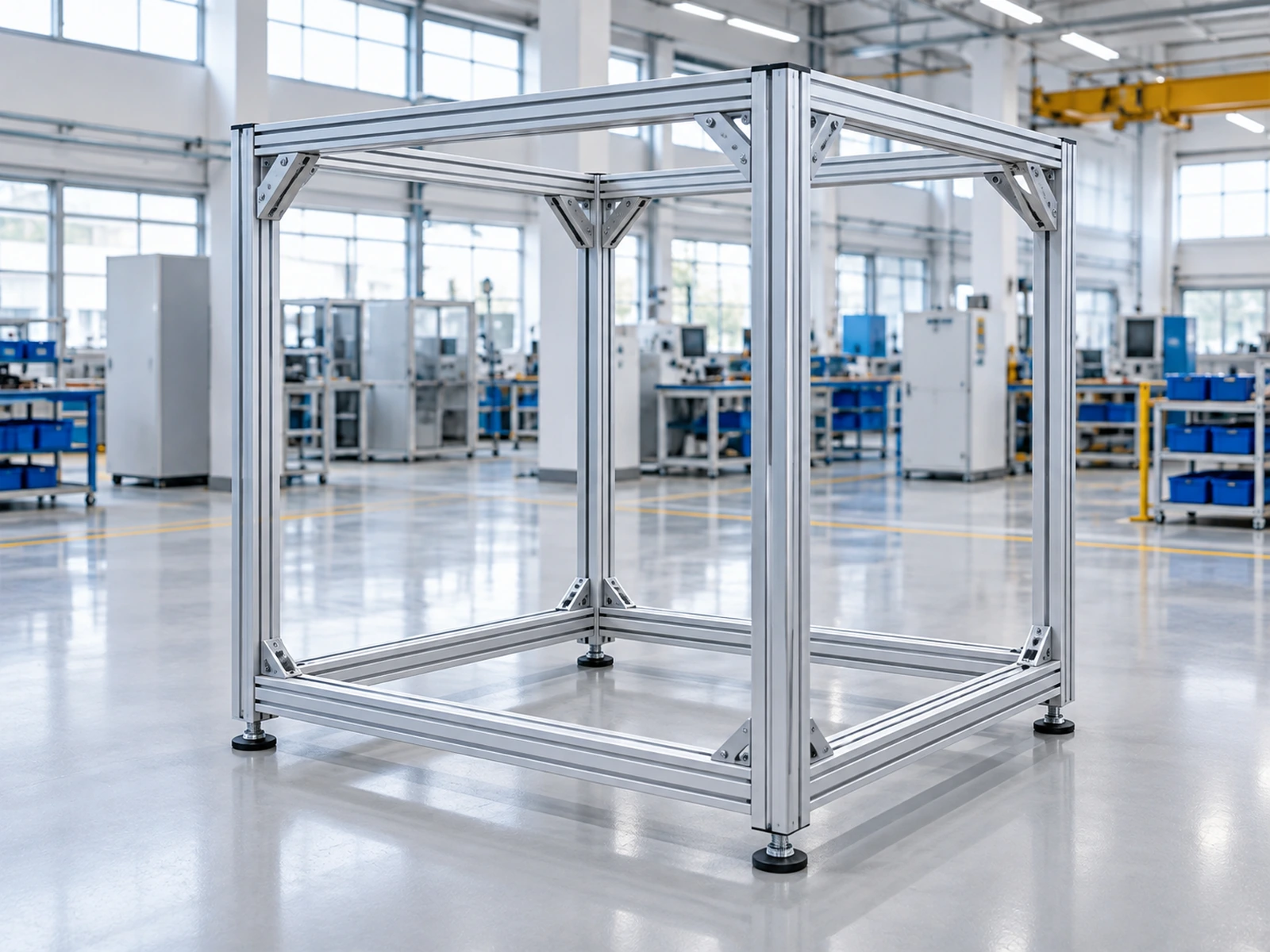
Which way should each member face?
Two pieces can have the same profile and finished length while requiring different feature orientations. An access hole or panel groove may need to face a particular side of the assembly.
Give each member a stable identity. Show its reference face, end labels and feature positions on the drawing when needed. Carry that identity into the next operation and the assembly kit.
For a rectangular profile, a rotated section can change the frame arrangement. For profiles with asymmetric features, make the intended orientation especially clear. A small end-view drawing often communicates this more easily than a paragraph of instructions.
Discuss locating, support and clamping with the machine supplier using the actual section. Follow the machine manufacturer’s approved setup procedure. Include visible-finish concerns in the trial requirements if the profile faces remain exposed.
Use the visible-surface handling guide to prepare the surface and handling questions that belong in a representative review.
Keep mirrored members distinct
Suppose a left and a right member share one cut length but receive opposite access-hole positions later. The cutting schedule can group their common cut geometry, but the machining and kit records must preserve the left/right identities.
This grouping is useful only when the approved production plan keeps the later features clear. Do not merge two part numbers simply because their saw-cut blanks look the same.
What should inspection and assembly verify?
For T-slot aluminum cutting, define part checks before the batch starts. Include finished length, required end geometry and the surface condition relevant to the assembly. Let the drawing and quality plan set the acceptance limits.
Check connector preparation separately where it is part of the delivered scope. The correct cut length does not prove that a threaded bore, access hole or other feature is in the correct position.
Use a representative assembly review when it is part of the agreed trial. Confirm that members correspond to the bill of materials and that the selected connections can be assembled as drawn.
If the assembled frame does not match the design, compare the measured parts, connector interfaces and member arrangement with the controlled drawings. Avoid changing cut lengths by guesswork to hide an unresolved drawing or assembly issue.
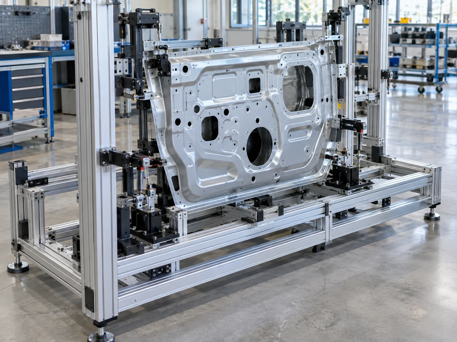
Deliver a complete assembly kit
Group members by frame or subassembly when that helps the recipient. Include part labels and quantities, and keep any pieces awaiting inspection separate from released kits.
If connector hardware is included, identify its exact reference and quantity. Make the scope clear: cut members only, prepared members, a complete kit or an assembled frame are different deliverables.
What to send for a frame cutting review
Send the profile cross-section, member drawings, assembly drawing and typical order quantities. Include the connector references and identify the operations that follow cutting.
JiurunCut can use those details to discuss a T-slot aluminum cutting configuration and a representative part trial. The review should cover the actual parts, handling arrangement and accepted-output requirements.
References and scope
Connector examples: 80/20, Standard End Fastener 20-3895 and Fastening Methods. The 600 mm frame calculation is an original illustrative example. Images show concepts and do not certify frame strength, connector compatibility or JiurunCut machine capability.