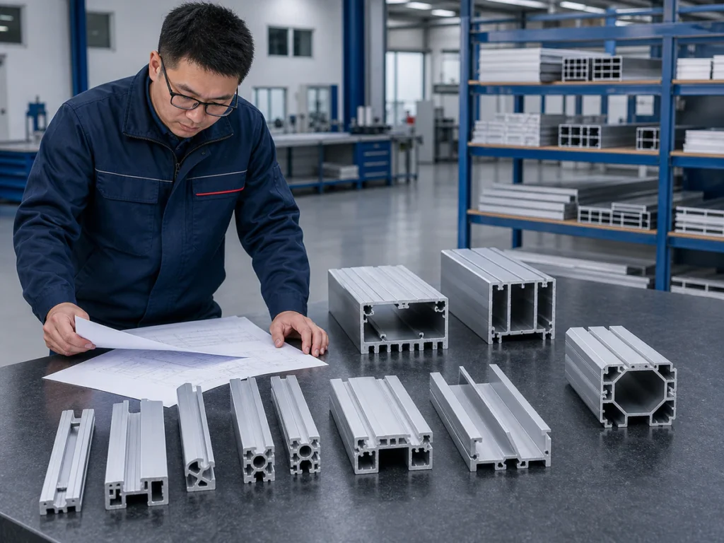
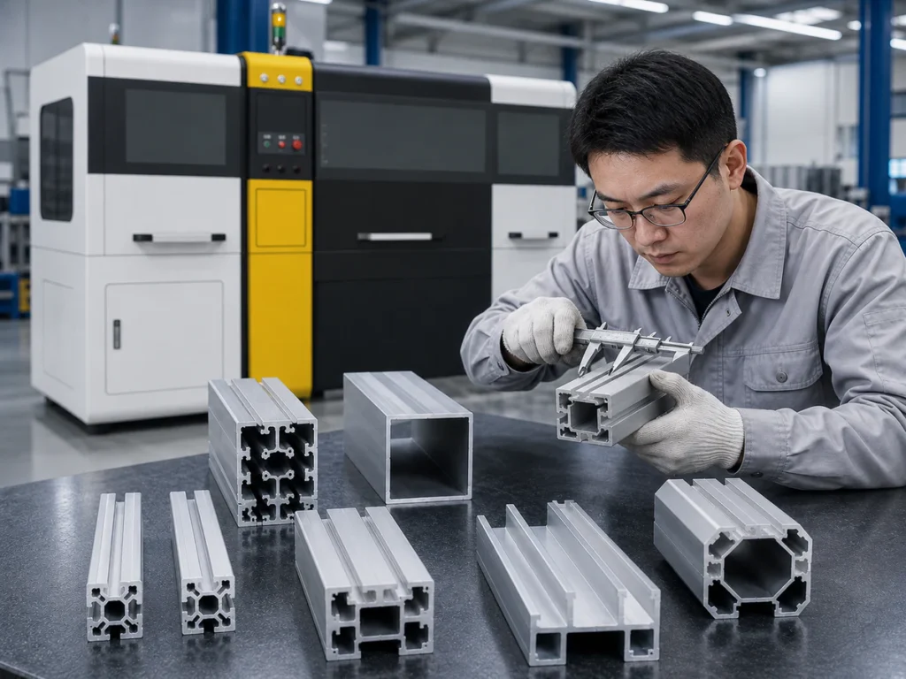
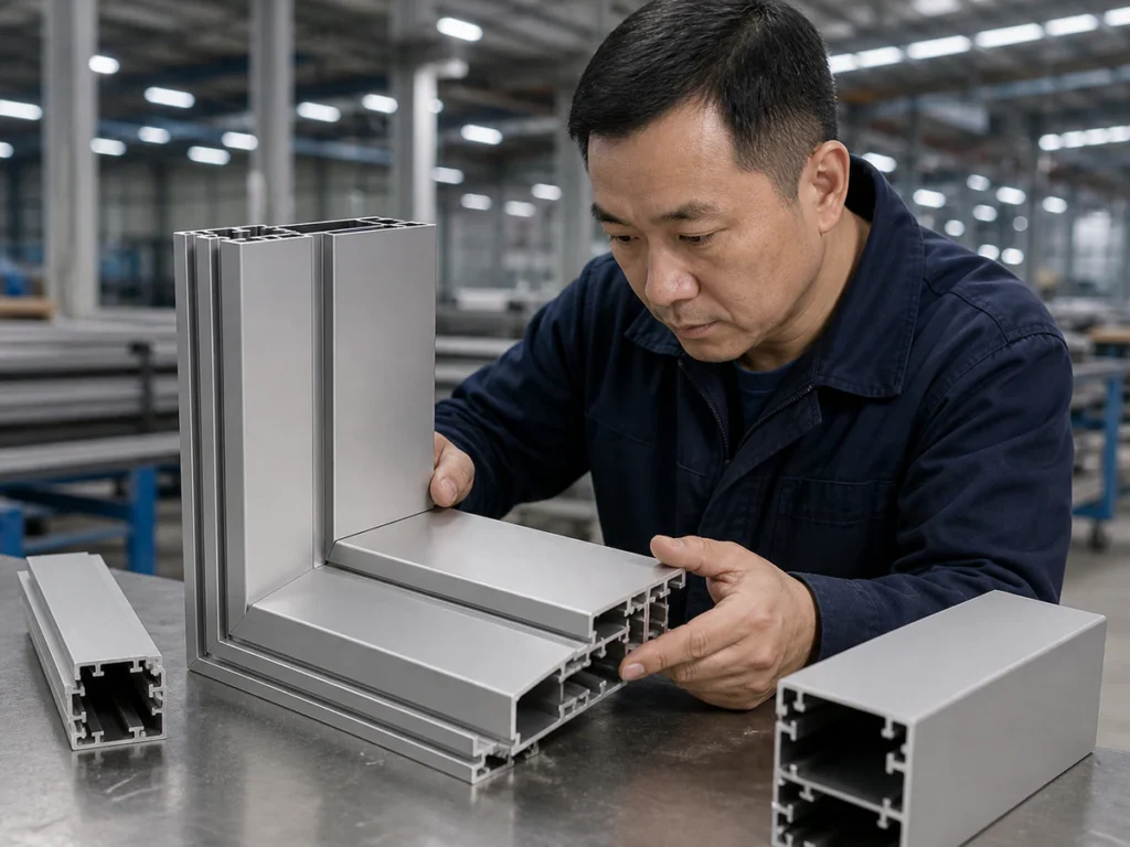
Before setting up an aluminum miter cut, define the finished joint, how its angle is measured, and which edge establishes the finished length. Mark the profile's orientation and visible faces too. A request for a 45-degree cut leaves important details open unless the drawing also shows the direction, handedness and measurement reference.
Three things to remember
- Show the finished joint and angle reference, not just an angle number.
- Identify long-point or short-point length and mirrored parts.
- Check the finished dimensions and a representative joint separately.
On this page
Why should the finished joint come before the machine setting?
The joint shows what the two finished members need to do together. Use it to establish the required cut direction, the surfaces that meet and the profile's orientation.
A datum is the reference face or edge used for measurement. Make that reference clear before selecting a displayed machine angle, especially when two similar-looking parts are mirror images.
Which four details belong on the drawing?
Show the joint, the angle convention, the start and end points for length, and the orientation of the section. Mark appearance-critical surfaces at the same time.
| Drawing item | What it prevents you from assuming |
|---|---|
| Angle reference | Whether the number describes a cut face, a machine setting or a joint |
| Long-point / short-point dimension | Which edge establishes finished length |
| Handedness and orientation | Which side of an asymmetric profile faces the fixture |
| Mating or visible surfaces | Which features must remain aligned and unmarked |
The long point and short point are the longer and shorter edges created by an angled cut. Stating which one is dimensioned avoids two people checking different lengths.
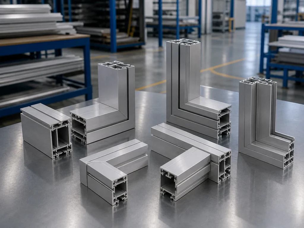
Keep the customer's established drawing and inspection conventions. An informal sketch can explain a question, but should not silently replace the controlled requirement.
Is a joint angle the same as the number on a machine display?
Not necessarily. Two matching miter faces may divide a simple symmetrical corner equally, but that geometry does not establish how a particular machine labels its position.
For example, a symmetrical right-angle corner can use two complementary mitered members. This illustrates the joint geometry; it is not a recommended machine setting.
The supplier still needs the intended orientation and length reference. For uneven joints or mixed angles, identify every required part and mark mirrored pieces so the correct cut is made in the correct direction.
Will the profile fit at the angle you need?
Check the actual combination of section, angle, finished length and allowed contact faces. A published angle range does not establish the complete usable space around the supported and clamped profile.
A maximum cutting dimension quoted for one condition should not be assumed to apply unchanged at every angle. Include the way incoming stock will be handled too.
List quantities and how often angles change. This helps compare recurring programmed work with occasional operator-loaded jobs without assuming one approach is always preferable.
How should visible faces and supports be considered?
A fixture is the arrangement that supports and holds the part. The face that looks best in a photograph is not necessarily the face that should locate an architectural profile.
Mark visible surfaces separately from the measurement reference. Review support near the cut, along the stock path and during collection.
Also decide how left- and right-handed members will stay identified. A correct angle does not prevent scratches or part mix-ups after cutting.
Fixture, guard and setting changes belong to the approved setup procedure. Do not improvise clamping or expose a moving blade to investigate a joint.
What should the sample inspection check?
An angle reading and a length reading answer different questions. Tie both to the agreed reference and use the drawing's tolerances, the permitted dimensional variations.
Where assembly matters, check a representative joint: its mating faces, seam relationship and intended locating features. This adds practical context without replacing dimensional checks required by the drawing.
Record part identity and drawing revision. One attractive corner photograph does not qualify every angle, section or setup.
How can you compare angle-cutting proposals fairly?
Keep each machine's photograph, structure and technical data together. Jiurun's supplied brochure contains different angle-cutting configurations whose capacities and ranges are specific to that configuration.
Do not take an angle range from one table and combine it with another machine's feeding arrangement. Use the applicable quotation and current product documents to establish the proposed scope.
The corner-cutting equipment range can help identify machine directions. It does not replace a review of the real joint and angle list.
What information makes an angle-cutting review clearer?
Gather the section, finished-part and joint drawings, angle list, quantities, stock lengths and inspection method. Mark visible faces, permitted contacts and any mirrored pieces.
For architectural projects, continue to the curtain-wall cutting solution. For the rest of the purchasing comparison, use the machine selection guide.
What else should you know?
Does a programmed angle prove the finished angle is acceptable?
No. Verify the finished part using the agreed reference and method. Programmed position is one part of the process, not the acceptance record.
Can a straight-cutting configuration be assumed to handle miters?
No. Confirm the machine's intended angle capability, fixture and work envelope.
Should all parts use the same length reference?
Use the reference specified for each controlled part. Keep it explicit and consistent between the drawing, setup and inspection.
Sources & Scope
- Jiurun machinery brochure supplied by the owner. 九润画册 PDF physical pages 6–19. Machine categories and configuration identity only; not test results or an operating manual.