
Imagine a buyer looking at triangular aluminum frame members on a drawing. A horizontal base joins two sloping members, which meet at an off-center top corner. The sloping sides have different lengths. All three corners in this illustrative design use mitered joints; other triangular frames can have different joint arrangements.
The buyer’s first note says “angled frame members.” A clearer inquiry names the base, left-side member and right-side member, then shows where each end belongs. That simple member map gives the supplier a much more useful picture of the cutting job.
Have a triangular frame to cut?
Send a complete frame drawing or a clear overall photo to start the discussion.
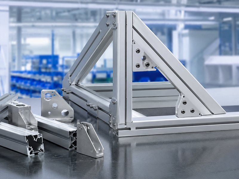
Follow the members around the triangle
Read this example from the front. The top corner is the apex. The lower corners are the left base corner and right base corner. Keep those names on the sketch so the member descriptions refer to the same view.
| Member | Connection at one end | Connection at the other end |
|---|---|---|
| Base | Left-side member at the left base corner | Right-side member at the right base corner |
| Left-side member | Base at the left base corner | Right-side member at the apex |
| Right-side member | Left-side member at the apex | Base at the right base corner |
The apex joins the two sloping members. Each lower corner joins the base to one sloping member. Across the whole frame, six member ends form three mating pairs.
Why triangular aluminum frame members need their own end patterns
The base has an end for each lower corner. The left-side member combines a left base end with an apex end. The right-side member combines an apex end with a right base end. Each member therefore needs a description of both ends, connected to its place in the frame.
Describing only the top joint leaves the lower ends of the sloping members undefined. Describing only the base leaves the apex pairing undefined. The useful inquiry follows each member from one connection to the other.
In this off-center example, the two sloping members stay separately named. Their different positions and lengths are part of the design. Using the same profile section throughout the frame still leaves separate member definitions and end combinations to communicate.
For the wording used beside the ends, our aluminum miter-angle guide covers angle references. The mirror-image parts guide covers opposite-hand descriptions.
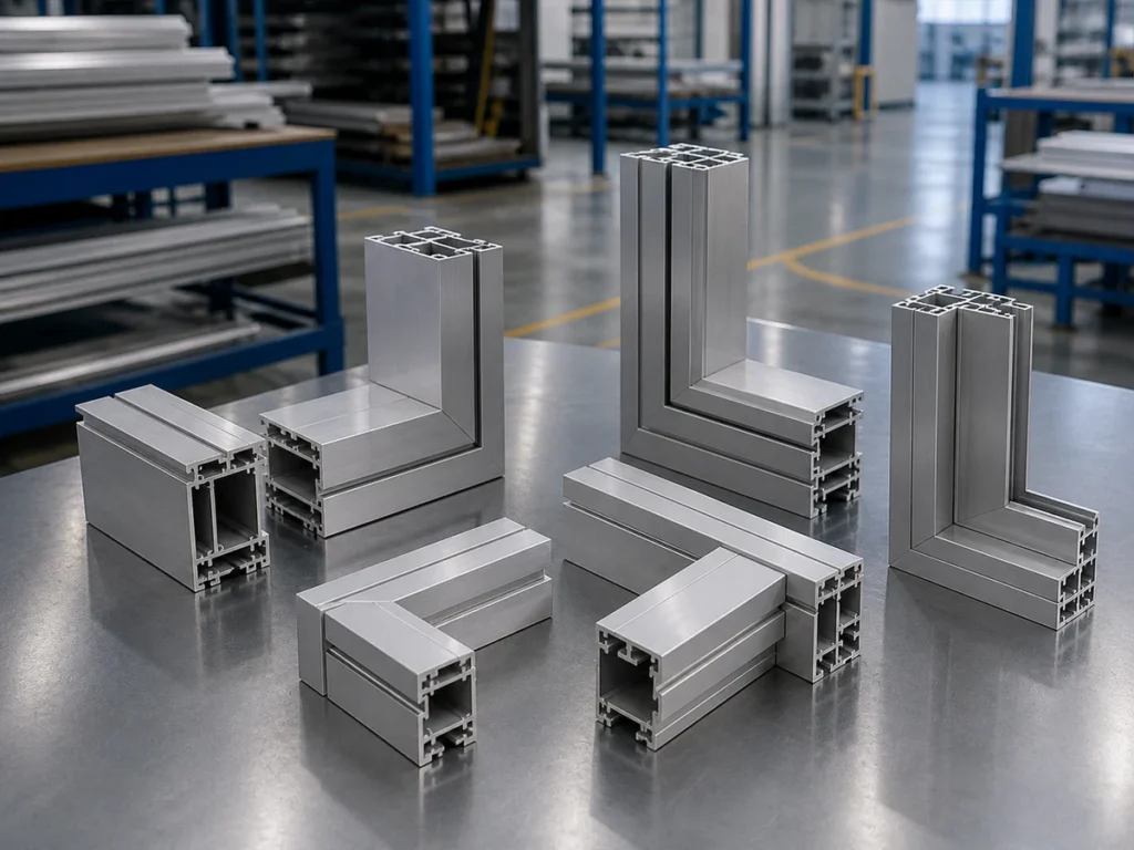
Send the whole frame with the member map
Show the base and both sloping members, including the connections at their ends.
Keep the complete frame in view
A close photo of the apex can introduce the shape, while an overall view explains how the base closes the triangle. Send both views if they help. Add the member drawings when available so the supplier can relate each loose part to its installed position.
Include the profile section and the joining details used in your design. If plates, connectors or other items join the members, show their relationship to the ends. Identify any holes or other preparation that belongs to a later operation. This helps describe what the saw-cut members contribute to the complete assembly.
Use the member map for the machine inquiry
The JR-550CNC-CORNER product page is a starting point for discussing this non-rectangular part family. Our automatic multi-angle machine buying guide covers the wider equipment decision.
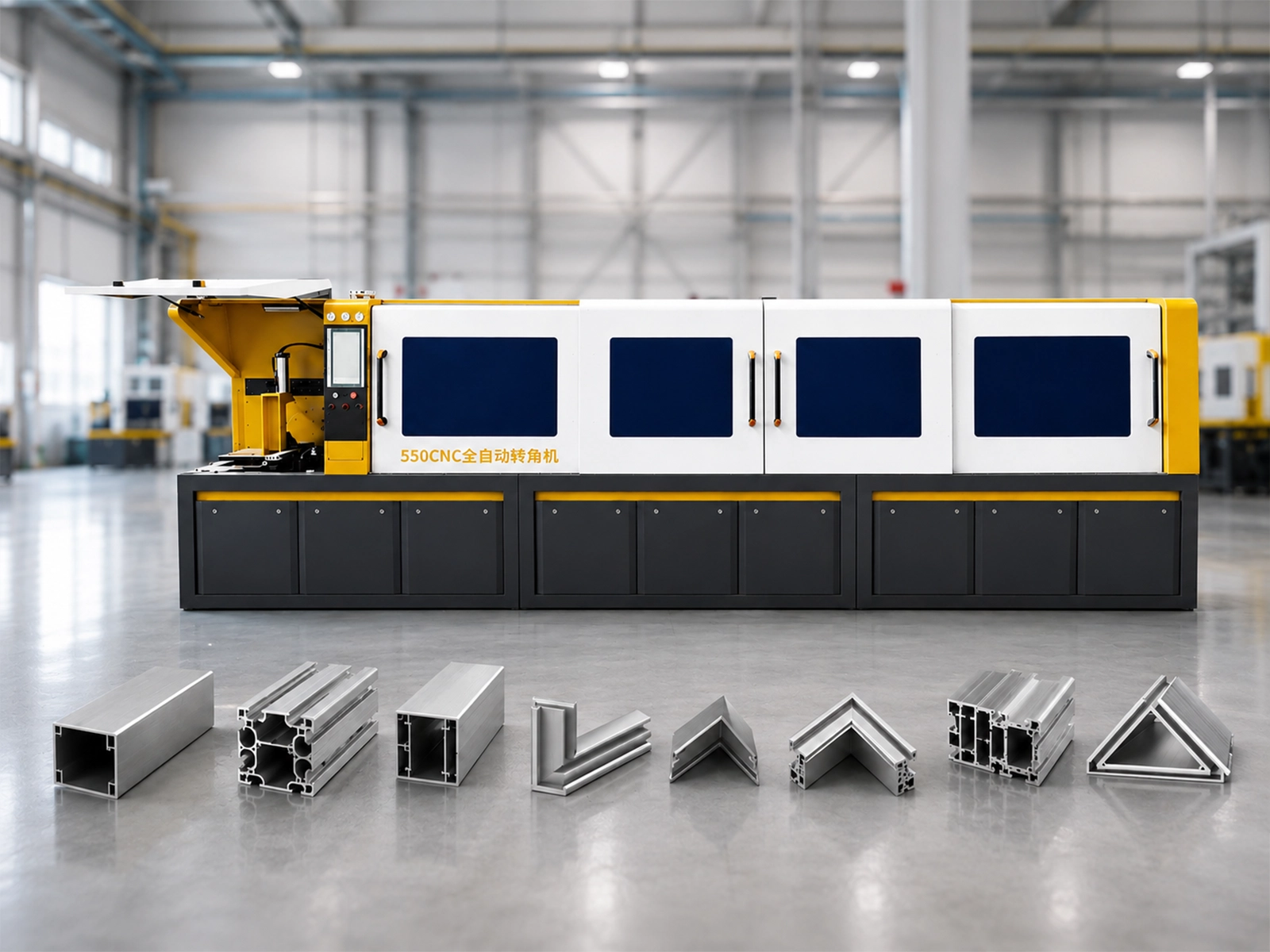
Watch: JR-550CNC Fully Automatic Angle Saw
General Jiurun angle-saw reference.
Catalog context and example scope
Jiurun’s catalog identifies JR-550CNC-CORNER and lists automatic feeding, positioning and cutting. The triangular frame is an editorial geometry example. Confirm cutting suitability for your actual member drawings and profile on the exact JR-550CNC-CORNER configuration quoted.
Discuss your triangular frame members with JiurunCut
Share the complete shape and the base and side-member definitions to begin a focused cutting-machine inquiry.