
Mirror-image aluminum parts need more than matching overall length. A left and right member may have different end directions, feature locations or assembly relationships. The buyer and supplier need to agree what defines each part before preparing the cutting route.
This guide walks through four practical checks for an order containing opposite-hand members. It focuses on the information passed from drawing review to cutting and inspection. The actual dimensions, machine setup and acceptance criteria must come from the approved documents for those members.
Make the handedness easy to see
- Name the viewing direction used to define left and right.
- Keep each part identity connected to its end and face references.
- Check the complete feature relationship before treating parts as interchangeable.
On this page
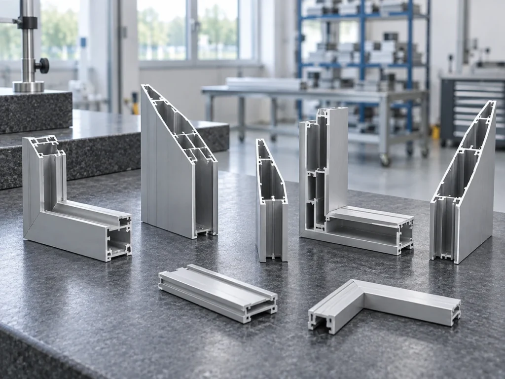
Are these copies or opposite-hand versions?
Start by asking what the designer means by “mirrored.” Does the assembly use two copies of one part in different positions, or does it need two different opposite-hand geometries? Those descriptions can lead to different drawings, part identities and manufacturing routes.
An official SOLIDWORKS explanation of opposite-hand parts describes creating a mirrored version about a selected face or plane. It also explains that the new version can retain a relationship to its original model or have that link broken. That is a CAD distinction to clarify with the designer; it does not establish how a particular saw processes either version.
Request the approved drawing or model for each required identity. If one document covers both variants, it needs to make their differences understandable. Avoid asking a workshop to infer the opposite-hand features from a single photograph or a note that merely says “make the other side.”
Two members may look similar on a bench while differing at an assembly interface. Conversely, a symmetrical member may legitimately be used in both positions if the approved design specifies that use. Confirm the design intent before creating unnecessary variant records or merging distinct ones.
Check 1: fix the viewing direction for mirror-image aluminum parts
Left and right need a shared viewpoint. A person looking into a frame can describe the sides differently from someone looking out of it. Use the drawing’s orientation and describe which side of the assembly the reviewer is viewing.
Identify a stable reference face and the part’s installed orientation. Where needed, show the visible face, inside face, top and bottom in the approved views. This helps the reviewer distinguish an actual change in geometry from a change in how the same piece is being held.
Use a marked drawing view or approved orientation sketch in the inquiry. Photos can help explain the physical profile, but they may hide a groove or flatten the apparent slope of an end. Keep the drawing as the reference for the feature requirements.
Ask the supplier to repeat the intended orientation in its proposed review record. The purpose is to expose differences in interpretation before the stock reaches the machine. Do not rely on matching informal words while everyone is picturing a different view.
Check 2: identify both ends and their references
Label the ends using the approved identification system. “First end” can describe a process sequence, while “left end” can describe an assembly position. Clarify which meaning applies so an operation record cannot silently substitute one for the other.
For a mitered member, show the end direction and the dimension reference. Two parts with the same stated angle and nominal length can still describe different end arrangements. Long-point and short-point references need to remain connected to the correct face and end.
The miter-length review explains why the measurement reference matters. Use that review with the actual drawing rather than assigning a generic sign to a machine’s angle display.
A machine may express its angle relative to a different reference from the drawing. Ask the supplier how the required end geometry is represented for the proposed model and configuration. Confirm the conversion with the responsible reviewer instead of assuming that plus and minus labels have a universal meaning.
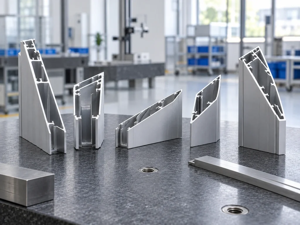
Check 3: follow the complete part route
Separate the cut blank from the finished member. Two identities might begin with the same blank and become different during drilling or another operation. Other identities may already need different cut ends. List where the variants actually diverge.
Include holes, slots, mounting faces and surface requirements in that review. Equal length alone does not establish that a member can be exchanged with its opposite-hand version. The assembled relationship of these features needs to match the intended identity.
Describe the stock orientation for the cutting proposal, including profile features that matter to support and clamping. Ask the supplier to review the actual cross-section and finished-end requirement. This discussion does not authorize a particular manual flip or handling sequence during operation.
If the inquiry includes model files, confirm what the supplier can review and what its equipment can import. A mirrored CAD model is design information; it is not proof of automatic program conversion. The cut-list import checklist helps separate drawing files, list fields and machine input requirements.
A clearer handover conversation
Consider this fictional planning conversation. An order names member LH and member RH. The cutting list shows the same nominal blank length for both, but their final drawings identify different feature relationships. No production or acceptance result is implied by this example.
| Unclear instruction | Question to resolve |
|---|---|
| “Use the same length.” | Are both cut-end arrangements also identical at the blank stage? |
| “Turn the part around.” | Does that orientation match the approved face, end and feature references? |
| “Make the mirror.” | Which approved identity, drawing and opposite-hand geometry are required? |
A good handover answers those questions with the relevant documents and references. It avoids turning a drawing interpretation problem into an improvised shop-floor instruction. Record any unresolved point before treating the manufacturing route as ready.
If the approved review confirms a common blank, that common stage can be described explicitly. The later variant operations still need their own identity and controls. If it confirms different blanks, preserve the distinction at cutting as well as at the later stage.
Check 4: release the correct part identities
Inspection needs to confirm the identity and required features of the finished variant. A length record without the handedness and reference information may not answer the assembly question. Keep the drawing revision and applicable inspection method connected to the result.
Use the agreed marking and separation method through handling and packing. The method should identify the variant without damaging a visible surface or making an unapproved permanent mark. Do not assume that every profile can be marked in the same way.
Reconcile the quantities by identity. Enough total pieces do not necessarily provide the required combination of left and right members. For assembly sets, use the frame-kit checklist to connect each required member to the correct set.
If a variant fails a check, keep its status separate from the accepted identity. A visually similar member should not be substituted without an approved decision that covers the complete requirement. This keeps the next stage from discovering an identity problem only during assembly.
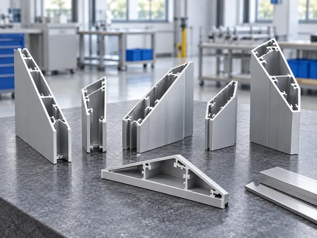
What to include in the machine inquiry
Send the approved LH and RH drawings or the document that clearly defines both. Include the cross-section, finished-length references, end directions, variant quantities and relevant downstream operations. Identify any shared blank stage that has already been approved.
Ask for a review of the proposed configuration and representative samples for each required geometry. Confirm what the sample review covers, how identities will be recorded and which requirements will be inspected. A demonstration of one member does not automatically establish suitability for the other.
Share the profile and variant requirements with JiurunCut for a cutting-machine discussion. State the actual differences between the parts so the review can address the proposed cutting route and its scope.
Buyer questions about opposite-hand members
Can I send only one drawing and request a mirror?
Provide enough approved information to define the required opposite-hand version. Confirm the mirror reference and affected features with the designer. The supplier should not have to invent the intended geometry.
Does equal length mean the parts are interchangeable?
No. Review end directions, features, surfaces and assembly relationships. Interchangeability comes from the approved design requirements, not from matching one dimension.
Should left and right always have different cutting programs?
That depends on the approved geometry, common blank stages and the proposed equipment. Ask the supplier to explain the route for each identity. Do not assume either a shared program or a separate one without that review.