
A rail length copied from a tracker drawing can look precise and still describe the wrong part. Solar tracker rail cutting begins with the module and tracker pairing that authorized that rail, not with a nominal millimeter value alone. One module may use a short bolted rail, another a longer support or a different clamp arrangement. The saw can produce an accurate blank for the wrong configuration. For an OEM buying cut aluminum members, the first release question is therefore: which controlled rail drawing belongs to this exact module, mounting method and tracker revision?
This guide concerns aluminum rail blanks made to a released customer design. It does not qualify a photovoltaic module, replace a tracker installation manual, or imply that Jiurun has tested any named tracker system. The module maker and tracker designer retain authority over the installed assembly.
The pairing comes before the cutting list
A useful cut order identifies the module model, tracker platform, mounting orientation, mounting method, rail part number and drawing revision together. It also states whether the saw supplier receives a bare extrusion, a previously punched rail, or stock requiring later drilling and coating. Those are different deliverables even if their overall lengths match.
Why insist on that chain? Canadian Solar’s PV module installation manual, revision 3.1, gives separate mounting instructions for bolted, clamped, insertion and single-axis tracker methods. Its tracker section links mounting details to the module configuration and calls out clearance around the junction box and bearing housing. These are examples from one manufacturer’s manual, not universal dimensions for every project. The applicable current module and tracker documents must be checked for the actual job.
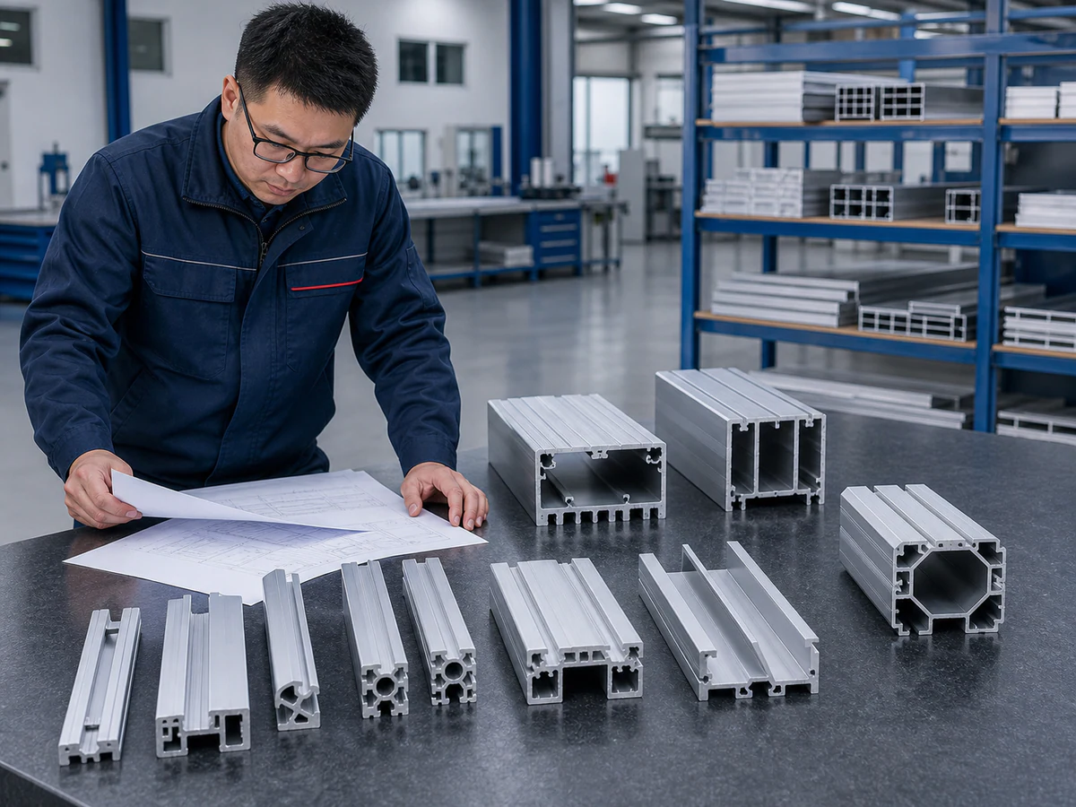
A buyer can put the chain on one order line: approved pairing reference → released rail drawing → extrusion stock and finish → saw blank length and datum → downstream operations → named assembly acceptance owner. If any arrow is missing, ask the design owner to resolve it before quoting the cutting cycle. A file titled “solar rail” is not enough to establish the pairing.
Separate the extrusion, rail blank and installed hardware
On a shop floor, “rail” can refer to three objects. The first is an extrusion with a cross-section and stock length. The second is a cut blank with defined end faces, length and perhaps a marked orientation. The third is the installed mounting member with holes, clamps, bonding hardware and controlled position relative to the module. A saw trial can inspect the second object. It cannot, by itself, prove the third.
The distinction is visible in the installation literature. ARaymond’s photovoltaic fastening information describes fastener and rail interfaces for tracker assemblies. Those interfaces depend on the selected fastening system. A cut face that measures correctly does not establish clamp engagement, electrical bonding, structural load capacity or service clearance. Those require the relevant component and system approvals.
If the work order includes post-cut holes or slots, identify which operation creates them and which datum controls their position. Do not silently treat a cut length as a hole-to-hole dimension. If the extrusion is asymmetric, identify which face rests on the saw support and which way the part will be oriented in the tracker. Mark the trial piece so that a reversed part cannot be mistaken for a passing sample.
Ask what the rail end can interfere with
Before cutting a first-off sample, the design owner should identify the neighboring module frame, junction box, bearing housing, torque tube, clamp and cable route on the approved assembly drawing. The rail end may need a clearance or a downstream feature that is invisible on a simple cut-length schedule. The Canadian Solar manual’s single-axis tracker section specifically addresses contact between a junction box and underlying racking and the position of bearing housings for a stated configuration. That is a reason to request the project’s assembly information, not a license to apply its examples to another module.
For a moving tracker, check the full travel and relevant load states in the system designer’s method, rather than deciding clearance from one static photograph. The saw vendor does not set the operating envelope. Its useful question is narrower: is the released blank length and end condition sufficient for the next operation without encroaching on a protected interface? When the answer is unknown, hold that cut revision for design clarification.
Solar tracker rail cutting has a clear first-off boundary
For solar tracker rail cutting, the first-off sample should be compared with the released rail blank drawing. Record the material identification supplied with the stock, profile orientation, saw support and clamp contact, length datum, cut-face condition, burr condition and any visible distortion. Measure from the datum the drawing specifies. If the rail is punched later, retain enough stock and identification for that route as instructed by the design owner. If the end face is later coated or machined, keep those acceptance steps separate.
For a repeated batch, check that the first and subsequent parts still correspond to the same drawing revision. A new module model or tracker hardware revision is not merely a new quantity on the same cut list. Ask for a revised release when a mating interface changes. This keeps a correct saw setting from producing a consistently wrong part.
The following Jiurun channel video shows an automatic aluminum cutting machine as equipment context. It does not show the rail, module pairing, clearance check or production approval discussed here.

The release decision belongs to two parties
The saw supplier can accept or reject the cut blank against the agreed drawing and inspection method. The module and tracker design owners decide whether the rail design, fastening system, loads, electrical interfaces and operating clearances are approved for the intended assembly. Keep those signatures distinct. A clean cut face cannot substitute for a tracker approval, and an approved tracker arrangement does not excuse an out-of-tolerance blank.
For a cutting inquiry, send the current rail drawing, the relevant module and tracker pairing reference, extrusion sample or section drawing, expected blank and downstream process, orientation and datum, batch mix, and the specific first-off inspection you want demonstrated. State which party owns the later hole-making, finishing and assembly checks. Our broader solar mounting rail cutting plan addresses the cut-list and kit flow; use this page when the open decision is whether the tracker rail belongs to the approved module configuration.
Need a saw-cutting review? Send Jiurun the released rail blank drawing and a representative extrusion section. We can discuss the cut stage and an equipment trial against those supplied requirements; system approval remains with the module and tracker owners.