
A frame member can leave a saw at the specified length and still stop at the next station: the connector catches at a cut end, the corner will not close, or a hole no longer lines up after assembly. For solar frame corner key insertion, the useful question is which condition the cutting supplier must release and which condition belongs to the connector, punch, press, or module-framing station. A saw trial should answer the first question with actual parts. It cannot, by itself, approve the completed photovoltaic module.
Trace the frame member through its real route
Do not assume that every solar frame uses the same corner joint. The MiniTec solar technology catalog shows distinct framing concepts, including corner-key preassembly and screwed frame arrangements. A fabricator therefore needs the approved extrusion section, mating corner part, joint method, and assembly sequence before using the phrase “ready for insertion.” If the customer has not fixed those items, a cut blank can be inspected against a provisional drawing, but connector fit remains an open decision.
Map the production route as named operations. In one route, sawed long and short members leave cutting for a separate punch and connector station. In another, a production line combines cutting with subsequent punching, connector installation, or riveting. The Aster line description and CGMA process description illustrate that these can be separate process modules. Neither description establishes the configuration of a Jiurun saw or the sequence used by a particular buyer. Put the handoff point and accountable station on the purchase drawing.
Release a cut end, not a nominal number
“Length 1000 mm, 45 degrees” is an incomplete instruction for a mitered member. The same nominal length may refer to the long point, short point, centerline, or a datum on the visible face. The connector cavity and the exterior frame corner also have a direction. A drawing should identify the measured feature, inspection side, left/right or long/short part identity, and permitted orientation at the next station. Otherwise a batch can be repeatable but consistently wrong for the chosen joint.
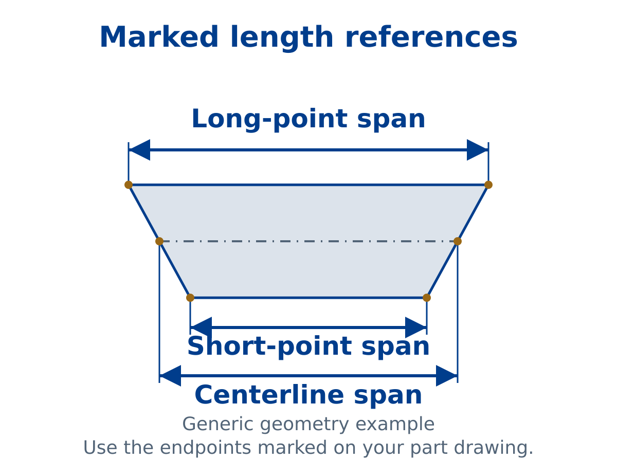
The end-face check should be tied to the actual key and profile section. Look for an open, accessible connector passage; burrs or displaced lips at the entry; face damage where the joint must close; and any clamp mark on an appearance or sealing surface. The acceptance limit for each item belongs in the customer’s profile and assembly drawing. A photograph of a tidy generic miter is useful for discussion, but it does not set a pass/fail limit for another extrusion.
Where solar frame corner key insertion begins
A useful handoff sheet names each stage, its input, and its proof. At the saw exit, the supplier can present labeled long and short members, a drawing-based dimension record, end-face photographs, and the cut conditions used for those samples. At punching, the responsible station can record hole location against the same cut-end datum. At connector insertion and pressing or crimping, the assembly owner can check entry, seating, closure, and any specified joint features with the approved key. Module framing, sealing, and final qualification remain further downstream. Keeping these records separate makes a failed corner easier to diagnose without attributing every defect to the saw.
If a connector sticks, inspect the actual contact location before changing the saw. A burr at the mouth, an incorrect member orientation, the wrong key/profile combination, a misplaced punched feature, or a press fixture problem can produce similar symptoms. Compare a labeled cut sample with the approved component set. Do not infer a cause from nominal angle alone. For the related but distinct question of pre-punched drain features, see our solar frame drainage-hole datum guide.
Run a trial that can answer the buyer’s question
Send representative straight stock from the intended extrusion family, including the longest, shortest, thinnest-wall, or most awkward member that matters to the order. Supply the approved drawing revision and identify the finish and cosmetic faces. The cutting trial should retain part orientation and label every sample so the downstream team can pair it with the correct corner key. A small sample of easy stock from another profile is insufficient to clear the interface.
Ask the assembly owner to try the cut samples with the actual connector and specified punch or press route. Record whether the key enters, seats, and permits the corner to close according to that owner’s acceptance method. If it does not, retain the failed pair and its measured end, hole, and key details. This is an interface trial, not evidence that a photovoltaic module meets sealing, mechanical-load, electrical, or certification requirements. Those questions require their own qualified process and tests.
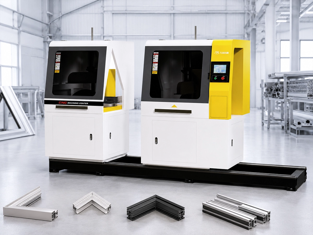
The short video below is from Jiurun’s own channel and shows a JR-455Q guarded aluminum cutting saw. It is a view of a related cutting station, not a demonstration of mitering or corner-key work. The footage does not show solar-frame stock, connector insertion, an approved configuration for this application, or performance proof for the trial described here.
For a useful first-article inspection record, put the member ID beside every measurement. A long rail and a short rail may have similar looking miter ends but different orientation or features. Photograph the connector entrance from a repeatable view, record which face was supported during cutting, and identify whether a later punch operation changes the edge being inspected. If the key trial fails, these notes let the saw and assembly teams compare the same physical part. If the key trial passes, retain the matched pair as a sample of that drawing revision only; do not quietly extend its approval to a revised cavity, finish, or connector. This simple traceability is often more useful than an isolated claim of machine accuracy.
What to put in the request for quotation
Give the saw supplier the section drawing and revision, finished profile condition, part-family list, cut-length datum, angle and orientation convention, output mix, and any end-face or cosmetic limits that affect the connector. State whether the supplier’s scope ends at cut members or includes transfer to a punch or assembly station. Name who will supply the corner keys and who will judge the paired fit trial. Request a sample record that identifies the stock, drawing revision, measured features, and any deviations. This prevents a quote for “solar frame cutting” from silently including an untested key-insertion promise.
If the interface is still being designed, ask for a cutting feasibility discussion first. Jiurun supplies industrial aluminum cutting equipment, but the right saw, fixture, and acceptance plan depend on the real section and target route. Send the profile drawing and intended corner-joint process to Jiurun so the cutting boundary can be discussed against your parts. Keep connector and module qualification with the parties responsible for those stages.