
Optical comparator vs CMM is a choice about the feature you need to inspect. An aluminum cross-section outline, a hole’s position relative to a mounting face and a pocket depth do not ask the same measurement question. Start with those requirements before requesting an equipment demonstration.
A conventional optical comparator presents an enlarged image for dimensional review. A coordinate measuring machine evaluates geometry from coordinate data using its configured sensors and software. The categories overlap: some coordinate systems use optical sensors, so “CMM” does not always mean a contact probe.
Choose the feature before comparing the equipment
Write down the characteristic, its reference and the part condition. For example, an extrusion’s end-section outline is different from the relationship between holes located along the finished member.
| Required check | What the provider should demonstrate |
|---|---|
| Visible section outline | How the relevant edge is presented, detected and evaluated in the selected view. |
| Feature-to-datum relationship | How the method establishes the required references and evaluates the named characteristic. |
| Depth or recessed feature | How the configured sensor reaches or resolves the feature without substituting a visible outline. |
This table is a starting point for an application review, not automatic approval of an instrument for a tolerance. A suitable proposal needs to address the actual drawing and representative part.
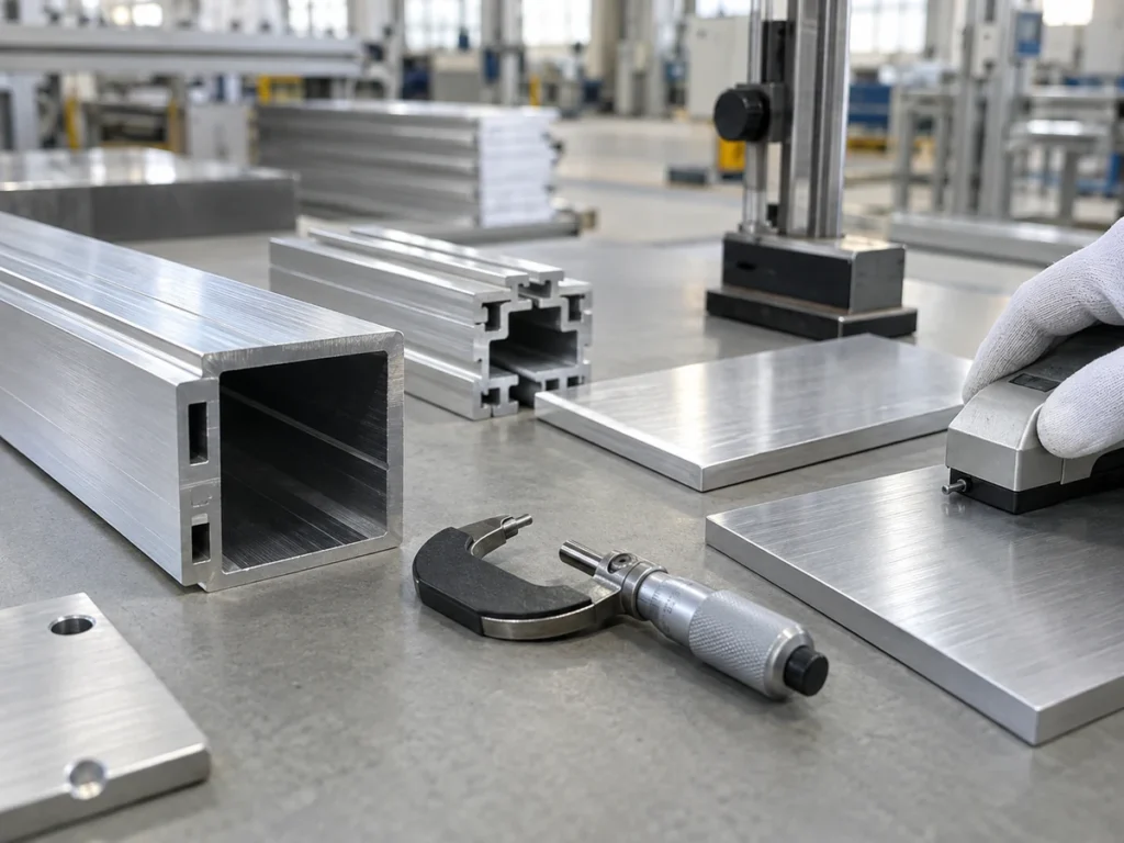
Optical comparator vs CMM: two measurement approaches
A conventional comparator presents a view
Mitutoyo’s product fundamentals guide, in its profile-projector section, describes optical comparators with horizontal or vertical arrangements. It explains stage-travel readouts, magnifying optics and options for profile or surface viewing. The viewing arrangement belongs in the equipment comparison.
The same guide discusses screen references and overlay charts. These are ways to compare the presented geometry. They do not mean that every visible detail is a complete three-dimensional measurement or that a familiar overlay is valid for a revised drawing.
Ask the provider to show the required edge in the proposed orientation. Identify which feature is being measured and whether another part of the workpiece obscures it. Do not assume that every visible line is the intended drawing boundary.
A CMM evaluates coordinate information
KEYENCE’s CMM overview describes three-dimensional coordinate measurement and distinguishes contact probes from non-contact sensing. It also explains that a workpiece’s reference system can differ from the machine’s coordinate system. For purchasing, sensor configuration and alignment matter more than the broad equipment label.
A result needs to represent the specified feature in the required reference system. The presence of three axes alone does not establish that a selected sensor can reach a recess, distinguish an edge or evaluate every drawing characteristic.
An optical CMM is a further category
KEYENCE’s optical CMM explanation describes camera and optical-sensor measurement and notes that some configurations add other sensing methods. Treat a vision system, a conventional screen comparator and a contact-probe CMM as identified configurations rather than interchangeable names.
Do not rank them using a universal claim about speed, accuracy or ease of use. Compare their demonstrated ability to answer the named inspection task.
Separate a cross-section check from a whole-part check
A cut end can make the extrusion outline accessible for review. That outline represents the inspected section. It does not, by itself, establish the geometry of every section along a long member.
For a long aluminum rail, distinguish an end-section size from a longitudinal feature relationship. A drawing can require both. Ask which locations the inspection plan covers and whether the planned method answers each requirement.
Also identify the state of the part. A raw extrusion, a saw-cut blank, a drilled rail and a coated component may expose different surfaces and edges. Use the condition required by the order when selecting the representative inspection piece.
For a finished housing, an outside silhouette can help show the external boundary while leaving an internal depth unresolved. This does not prove that all optical methods are incapable of depth measurement; it identifies the need to review the actual sensing arrangement for that feature.
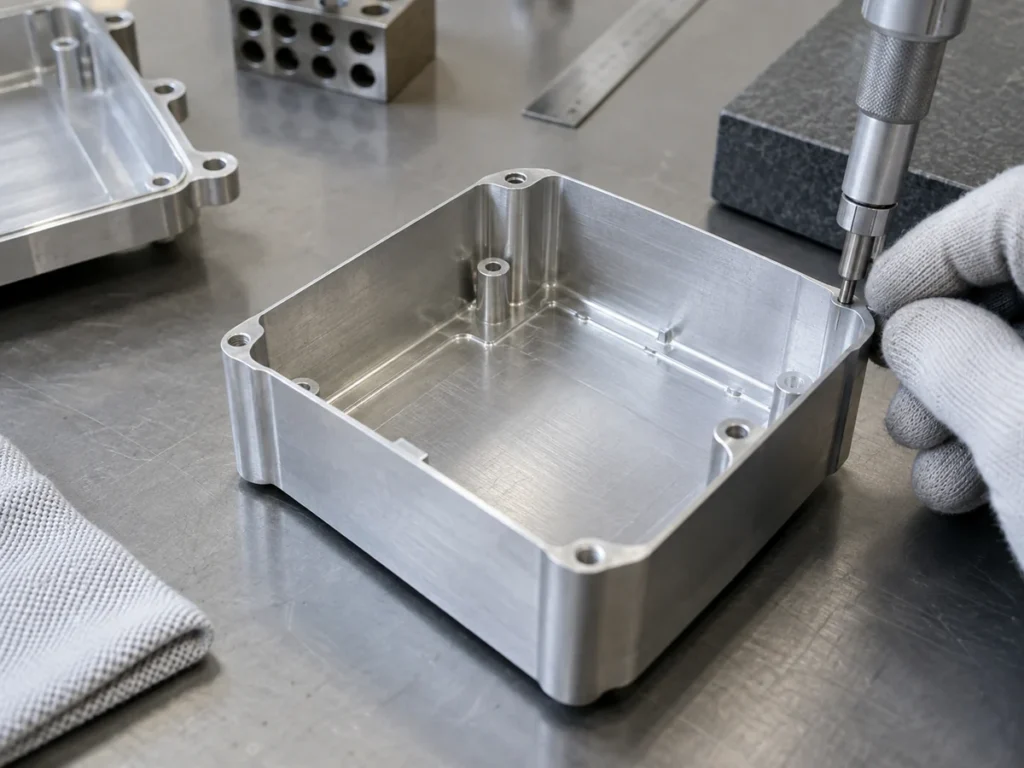
Ask the demonstration to answer three practical questions
Can the required feature be presented?
Bring the drawing and a representative part to the provider’s review. Include the most restrictive access or visibility condition, rather than showing only an easy external dimension.
For a projected image, have the provider explain how it identifies the edge used in the result. For a contact measurement, have it explain the contact locations and access. For a combined system, record which sensor evaluates each characteristic.
Does the reference match the drawing?
A local width between visible edges and a position relative to defined datum features are different results. Confirm the reference and evaluation for each reported characteristic. If a setup uses a convenient origin, ask how it relates to the actual drawing requirement.
Keep this review tied to the specific feature. It is not a request to invent a generic alignment for all aluminum parts. The responsible inspection provider should establish the applicable method.
Can the result be repeated and reviewed?
Review the setup, support, operator tasks and required records with the quality owner. Where the drawing or order requires uncertainty information or a decision rule, include that evidence in the method review.
A clear demonstration should show both what was evaluated and what remains outside scope. A polished screen image or automated pass label is insufficient if the selected characteristic is different from the requirement.
Compare the inspection workload
The price of the instrument is only one part of an equipment decision. Request the proposed work needed to prepare, support, measure and document the part. Include feature changes between product variants and how the approved method will be maintained.
For recurring section checks, ask how the provider handles the applicable drawing revision, reference material or program. For varied machined parts, ask what setup and evaluation work each new geometry requires. Compare those proposed tasks against your actual mix of parts.
Do not extrapolate a short demonstration into a promised batch inspection rate. Define what the demonstration included and ask for an application-specific proposal. This guide supplies no generic cycle time, price or tolerance threshold.
If you are comparing supplier inspection services rather than purchasing equipment, the same approach works: name the features and request the method and coverage. Different instruments can contribute to one inspection plan when their roles are clear.
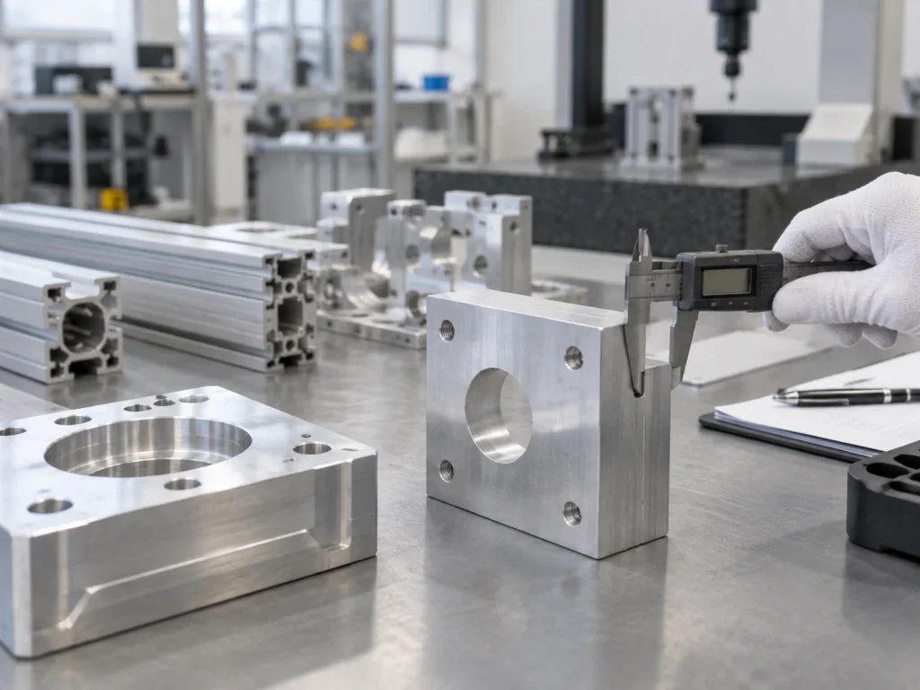
Keep the report connected to the method
Once a method has been selected, record the part identity, drawing revision, inspected condition and evaluated characteristics. Preserve the reference and sensor information needed to understand the results.
Our CMM report guide explains how to read submitted results. For accessible size measurements using hand tools, see micrometer versus caliper. Those checks complement equipment selection; they do not make a particular method suitable by name alone.
Quick selection questions
Is a CMM always more accurate than an optical comparator?
A universal ranking is insufficient. Review the configured system, measured characteristic, setup and supporting evidence against the actual requirement.
Can an optical system inspect a delicate feature without contact?
The sensing arrangement may avoid probe contact, but the feature still needs suitable presentation, support and evaluation. Confirm the complete method for the actual component.
Does JiurunCut provide the instrument shown in this guide?
The images are illustrative part-review scenes. They do not establish installed inspection equipment or an offered metrology service. Send your cutting drawing and required finished-part checks for a job-specific discussion.
A useful optical-comparator-versus-CMM decision names the features each method can evaluate, the evidence supporting that use and the remaining inspection work. That gives purchasing a clear scope and quality control a reviewable result.