
Use the finished member drawing to define an aluminum frame cut length. A panel size alone leaves the profile width, corner design and panel position unanswered. Send the assembled frame and the individual members so the machine discussion starts from the pieces you need to cut.
Panel size, opening and frame outside describe different things
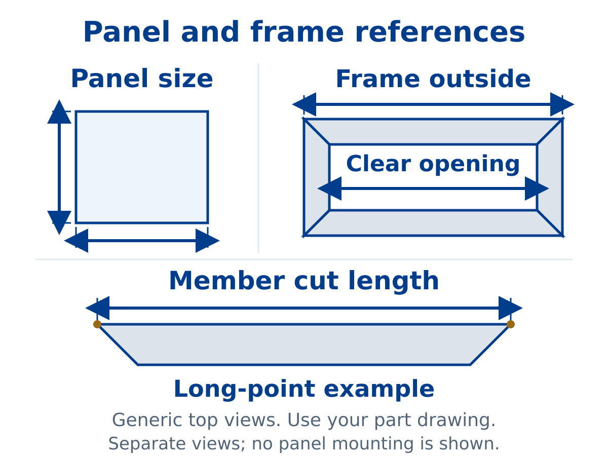
The panel size describes the sheet or insert. The clear opening describes the space between the frame’s inner faces. The frame outside describes the overall assembly. A member cut length describes one finished aluminum piece.
These dimensions can be related, but they should keep their names on the drawing. A number described only as “frame size” can leave the supplier unsure whether it belongs to the panel, the opening or the outer frame.
Do you have a panel drawing but no member cut list yet?
Share the frame concept and profile section so the missing member information can be discussed.
Show how the panel meets the profile
Include the panel’s position in the assembly. Does its edge sit within a profile feature, overlap the opening or rest on mounting hardware? Have the responsible designer define that relationship and the required fit.
A mounting arrangement can make the panel edge different from the clear-opening edge. The profile section and hardware therefore belong with the assembly view when the member drawings are prepared. Do not turn the panel measurement into a cut length without checking those details.
For example, a panel-mount bracket may place a panel flush with a profile. That is one reason to show the chosen mounting arrangement rather than assuming every panel uses the same edge position.
Take the aluminum frame cut length from the member drawing
For an angled end, identify the points that define the finished length. A drawing may use the longer edge, the shorter edge or another stated reference. Carry that same reference into the cutting list and inspection method.
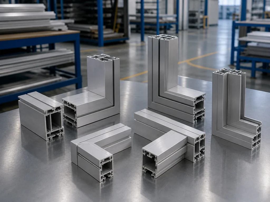
The illustration uses a long-point example, not a universal rule. Changing the corner design can change the individual members even when the panel itself stays the same. Review each finished member after such a change.
Our finished-length reference guide explains how to keep the measurement points clear.
Keep the assembly and the cut parts together
Send the panel drawing alongside the finished member views and their length references.
Use the member list for the cutting-machine proposal
List the aluminum members the saw must produce, with their profile sections, finished lengths, end directions and usual quantities. Keep the panel requirements visible as assembly context, while identifying the actual saw-cut parts.
Jiurun’s brochure identifies JR-550CNC-CORNER as an automatic corner-cutting machine. Use your member drawings to discuss the proposed cutting arrangement and the support needed for the stock and finished pieces.
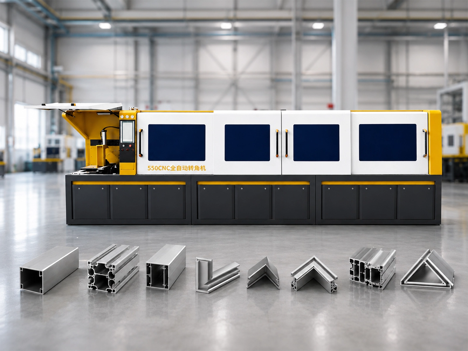
Ask how the proposed setup will be checked against those drawings. The multi-angle machine buying guide covers the wider equipment review.
Watch: Jiurun angle-saw demonstration
Use this machine reference when discussing the end shapes and length references of your frame members.
Discuss your aluminum frame cut length with Jiurun
Show the panel, the assembled frame and the pieces that need cutting. A clear member drawing helps the machine inquiry move forward.
For mounting context, 80/20’s panel-mount bracket description gives an example of flush mounting, with hardware chosen around panel type and thickness. Show your chosen mounting detail in the frame drawing. Jiurun machine context is in the brochure, physical PDF page 13, through Catalog & Downloads.