
A long aluminum extrusion cutting setup must support the stock before feeding, during clamping and after separation. Review the whole material path with your actual section and lengths. These five checks help you assess floor space, fixtures, feed travel and collection together.
Three things to remember
- Show the full length of the incoming stock and the longest finished part.
- Agree where the length datum and stable clamping points will be.
- Check a representative first piece and the material left after cutting.
On this page
1. Map the long aluminum extrusion material path
A blade-size comparison answers only one part of the question. Draw the route from the incoming bundle or rack through loading, feeding, cutting, collection and the remaining stock. Mark any point where a long extrusion would extend beyond a support.
Include the actual available floor space and the direction in which stock enters. An arrangement that works in a product photograph may be awkward next to your racks, aisle or downstream operation. Ask who will position the first length and remove the final remnant.
- Incoming stock lengths and variation
- Longest and shortest finished pieces
- Support positions before and after the cutting zone
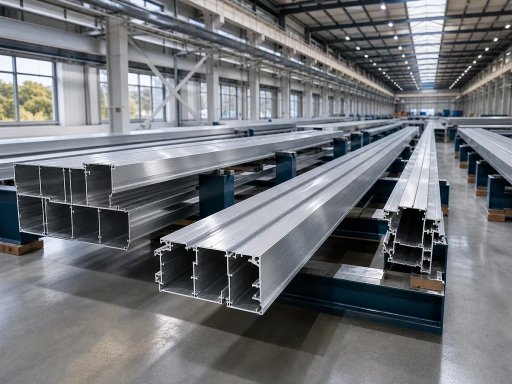
Sketch the cell to scale before ordering. Mark the incoming rack, loading direction, feed path, cutting zone, collection area and space needed for the final remnant. Add the longest stock you use. A long aluminum extrusion may extend well beyond the saw enclosure; the layout review should include that material and the operator actions around it.
2. Review the section before the clamp
Long profiles can be narrow, wide, open or multi-cavity. A support under one section may contact another section in the wrong place. Send an end-view drawing and identify the surfaces that must remain unmarked.
The fixture should hold the piece consistently without asking a thin wall to carry all clamping force. Confirm how a new profile family changes the contact points and whether a different fixture is included in the proposed setup.
- Strong webs or base areas available for contact
- Faces that may be visible after assembly
- Profile families that need separate supports
3. Define feed travel and finished dimensions
State where the finished length is measured from. If an angled end is involved, name the reference face and end point rather than sending only one length number. The supplier can then propose a feeding and measuring method against the drawing.
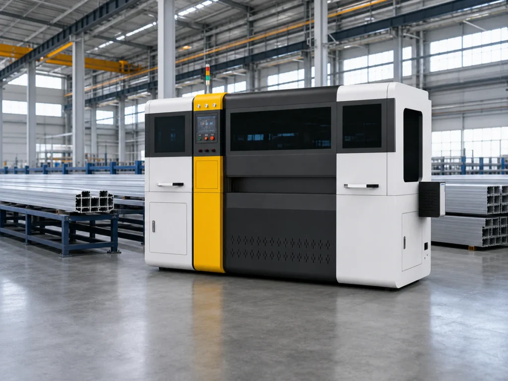
Do not infer usable feed stroke or maximum part length from a model name. Ask the supplier to show the proposed configuration for your actual stock and finished part, including the first and last usable cut.
- Drawing revision and units
- Straight or angled ends
- Length datum and inspection method
Stock and part length
Information to send: Actual incoming lengths and finished range
Question to ask: Can the proposed feed and support layout handle both extremes?
Cross-section
Information to send: End-view drawing and physical sample
Question to ask: Where will support and clamp forces be applied?
Acceptance
Information to send: Datum, tolerance and visible-face requirements
Question to ask: How will representative parts be measured?
▶ Watch: Long-Profile Feeding & Clamping
This video shows a machine setup example. Confirm the configuration against your own profile drawing and sample.
4. Test representative profiles and lengths
A useful trial includes a typical profile, a difficult profile and the length extremes that matter to the project. Record the setup used for each. One attractive short sample does not establish that the full-length feeding and collection plan is suitable.
Inspect the finished length, cut face and any contact marks using the acceptance method agreed before the trial. Keep the initial and late pieces identified if the job involves a repeated batch.
- Profile and stock used
- Fixture and feeding arrangement
- First, later and final-part inspection records
5. Compare the complete equipment scope
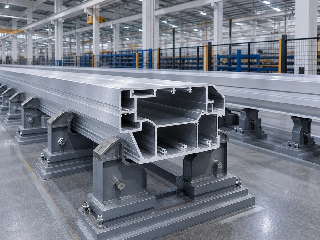
Ask whether supports, loading assistance, discharge tables, guards and changeover fixtures are included or optional. Compare what the operator must still do, not just the word automatic.
For complex structural extrusions, the rail transit cutting application shows the type of drawing, support and sample questions worth discussing. The extrusion cutting guide covers the wider profile review.
Common questions
Does a larger blade solve a long-profile problem?
Not by itself. Blade capacity, feed travel, support, clamping, collection and floor layout must work together.
Can one support layout serve every extrusion?
Only after the profiles and contact points have been reviewed. Different sections may need different fixtures or adjustments.
What can I send if I do not yet have a complete drawing?
Send a clear cross-section photo, approximate dimensions, stock length and the finished part you need. Mark unknown details for follow-up.
Discuss your cutting requirements
Send a long aluminum extrusion section drawing, incoming stock lengths and finished-part range. Include a simple floor-layout sketch and typical batch size. We can review support, feeding and collection as one configuration and identify what should be demonstrated in the sample trial.
References and scope
This is a planning checklist for industrial circular-saw cutting of aluminum extrusions. It does not state a capacity or guaranteed result for any specific JiurunCut model. Recommendations require a review of your drawing, sample and production requirements.