
Internal web burrs in multi-chamber aluminum extrusions can escape a quick perimeter check. An outer cut face may look clean while a thin web inside the section leaves a raised lip at a chamber opening. Whether that lip matters depends on what the opening must do next: accept an insert, clear a fastener, carry a wire, drain, or simply remain unused. The practical question is therefore not “Is every visible edge perfect?” It is “Which internal edge has a specified function, and how will the next station confirm it?”
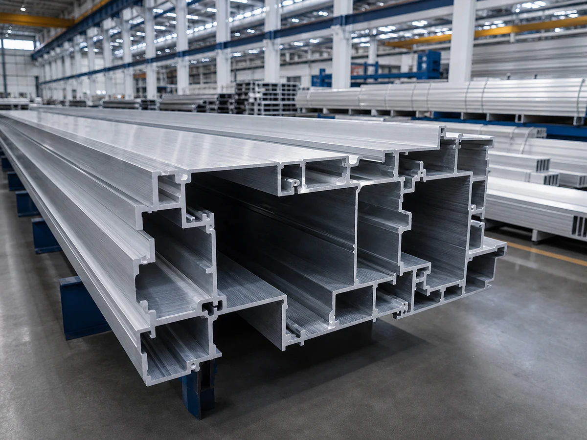
The featured image shows related, clean multi-chamber profile sections to illustrate the web geometry. It is not a record of a burr, a customer part, or a Jiurun cut trial. The release decision has three checks: mark the functional cavity, inspect the as-cut web, and validate the receiving fit. This guide sets out a drawing-led inspection and handoff plan for a representative saw-cut blank.
Where internal web burrs hide in a multi-chamber section
A hollow extrusion may contain several voids separated by internal webs. The Aluminum Extruders Council (AEC) describes hollow shapes with one or more enclosed voids and notes that section geometry affects extrusion design. After sawing, each web intersects the end face and adds an edge that an outside-only visual check may miss. The end that looks acceptable from one angle can still obstruct the exact cavity used by a downstream component.
Do not treat every chamber as equivalent. A connector may enter one large void while two smaller chambers are structural only. Another design may route a cable through a small passage. The responsible designer or assembly owner must mark the functional openings and define the relevant acceptance criterion; the cutting supplier should not invent a universal burr height for the whole section.
Mark the cavity that the next operation uses
Start with a released end-view drawing, not a photo of a generic hollow profile. Give the two cut ends names such as A and B, then label each chamber and any insert path. Mark the edges that can contact a mating part or trap a loose chip. Add the orientation of the profile during cutting, because the part may be rotated between the saw, the inspection bench, and assembly. A single marked end view makes a much better first-off reference than an unlabelled “deburr all” note.
- Insert or end plate: identify the chamber, entry direction, insertion depth, and the mating sample used for a fit check.
- Cable or service passage: identify the actual route and any edge that can contact the routed item. Cable protection is an assembly design decision, not a claim established by a saw photograph.
- Drainage or flow passage: mark the opening and the approved cleanliness method. Do not infer flow performance from a clean-looking cut end.
- Nonfunctional void: record that status explicitly so inspection effort stays tied to the approved drawing.
For clamping questions that arise from the same section, our multi-cavity extrusion fixture guide addresses support and deformation at the saw. The acceptance map here focuses on what remains at the internal web edge after the cut.
Capture the first-off before its condition changes
Inspect the first-off part in its as-cut state before an unrecorded brush, air blast, or hand-finishing step changes the evidence. Photograph both labelled ends with enough light to see the internal webs. Note the stock lot or profile revision, the saw setup reference, blade condition, and which face was supported. Use the same orientation and camera angle for a comparison sample. AEC notes that the need for deburring depends on factors including alloy, profile design, blade, and the requirements of the finished part; inspection therefore belongs to the actual section and process rather than a generic machine claim.
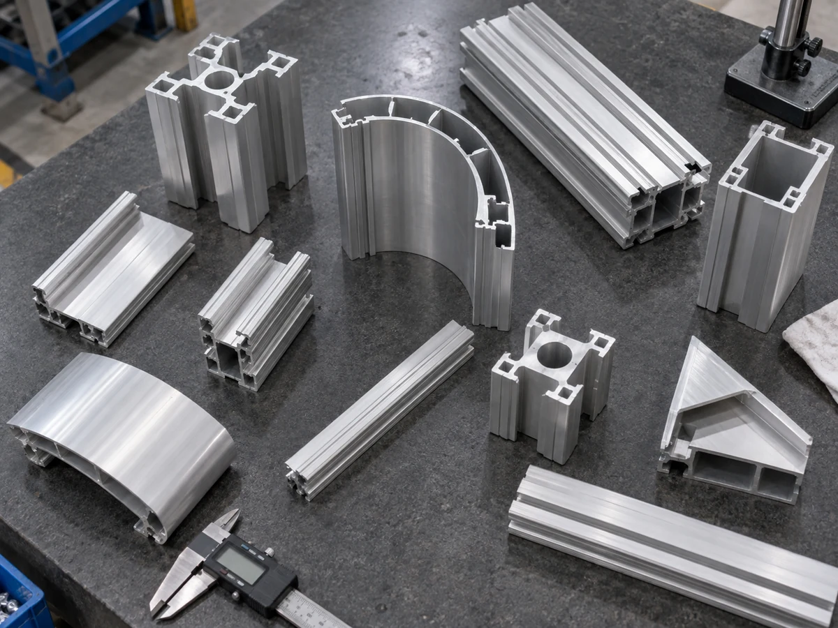
If an opening is too deep or narrow for a reliable naked-eye view, agree on a suitable method before the trial: a lighted end view, magnified image, accessible probe, or a section-specific mating gauge may be appropriate. AEC lists hand tools, video measurement, and coordinate measurement among possible inspection methods for extrusion work. The method must reach the nominated edge and resolve the feature being accepted. A caliper across the outer width does not prove that a hidden web is free of an attached burr.
Separate an attached burr from three other observations
A snag at a chamber entrance is a useful symptom, but it does not name its cause. Record what is physically present before changing the saw settings or adding a finishing operation:
- Attached burr: metal remains connected to a web or wall at the cut edge. Record its location and direction relative to the specified mating path.
- Loose chip: a separate fragment sits in a cavity. Cleaning and verification may be needed, but the condition is different from an attached edge burr. See our chip-removal handoff guide for that separate decision.
- Wall deformation: the chamber or lip has shifted under support or clamping. Deburring cannot restore the approved section geometry.
- Existing profile feature: a seam, extrusion texture, or designed rib is already present on the incoming stock. Compare an uncut stock end and the drawing before assigning it to sawing.
Do not force an insert through a suspect opening to make it pass. The force may fold a burr, damage a mating part, or hide which edge caused interference. Preserve a labelled failing sample alongside the first acceptable sample when the project owner needs to decide the disposition.
Use the saw trial to identify a controllable cause
Once the failing web and inspection method are known, trial changes can be compared one at a time. Check whether the actual profile is supported near the cut without closing a chamber or marking a functional face. Review blade condition, tooth and chip clearance with the approved tooling and machine instructions. Record a first-off from the agreed setup and check the same internal edges again. A cleaner outer face alone is not a successful trial if the functional cavity still fails its receiving check.

The Jiurun video below shows a general aluminum sawing operation. It helps a buyer discuss stock placement, support, and the sequence of a sample cut. The clip does not verify this article’s profile, internal-web burr, machine configuration, customer order, or achieved tolerance.
Release the part by named edges, not by appearance
The purchase specification should say who owns the as-cut inspection, any approved deburring method, cavity cleaning, and the final assembly fit check. If deburring is required, define the permitted edge treatment and protect the chamber dimensions and functional finish; removing metal without a limit can turn a burr problem into an insert-fit problem. The designer or receiving team should approve that boundary. AEC’s fabrication guidance places cutting among several operations that may precede final assembly, so a saw-cut blank should be released to the next station with its actual process state stated clearly.
For internal web burrs, a usable acceptance record has the drawing revision, end A/B labels, chamber IDs, close-up images, the agreed inspection method, the result at each functional web, and any disposition of failing pieces. State whether the check applies to every piece, the first piece after a setup change, or a sampling plan agreed by the customer. Recheck when the profile revision, blade, fixture, or downstream insert changes. This turns “no burrs” into an observable, repeatable handoff without claiming that one machine or blade removes every internal edge burr.
What to send for a useful cutting discussion
Send Jiurun the released multi-chamber section drawing, a marked end view showing functional chambers, a representative stock sample, the cut list, and any mating insert or receiving gauge. Include one labelled failing and one accepted end-face image if they exist. We can discuss the saw-side first-off and which internal web checks to demonstrate. The part designer and receiving process owner retain approval of the cavity function, deburring route, and assembly performance. Contact Jiurun with those inputs.
Technical references: AEC extrusion design tips; AEC cutting and forming; AEC FAQs on inspection; AEC fabrication overview.