
First angle vs third angle projection changes how related views are arranged on an engineering drawing. It does not change the part. A side view placed to the right of a front view can represent a different physical side depending on the declared projection method.
That difference matters when an aluminum member has an offset hole, a stepped section or unequal end features. Before discussing a cut, machining allowance or assembly fit, make sure both teams are looking at the same face.
On this page
First angle vs third angle projection: the layout difference
Read view placement relative to the selected base view. The following comparison uses a front base view and directly aligned orthographic views. It is not a rule for every detail, auxiliary or separately labelled view on a sheet.
| Declared method | Views beside the front base view |
|---|---|
| First angle | The view directly to the right shows the left side. The view directly below shows the top. |
| Third angle | The view directly to the right shows the right side. The view directly below shows the bottom. |
Autodesk’s projection-angle documentation explains these relationships for projected drawing views. It also describes defaults associated with its drafting-standard settings and allows an override. Check the actual drawing rather than inferring the method from a country, supplier address or software name.
A useful mental question is: “From which physical side am I viewing this part?” The answer comes from the declared convention and view identification together. “The picture on the right” describes a position on the page, which is insufficient when the projection method is unresolved.
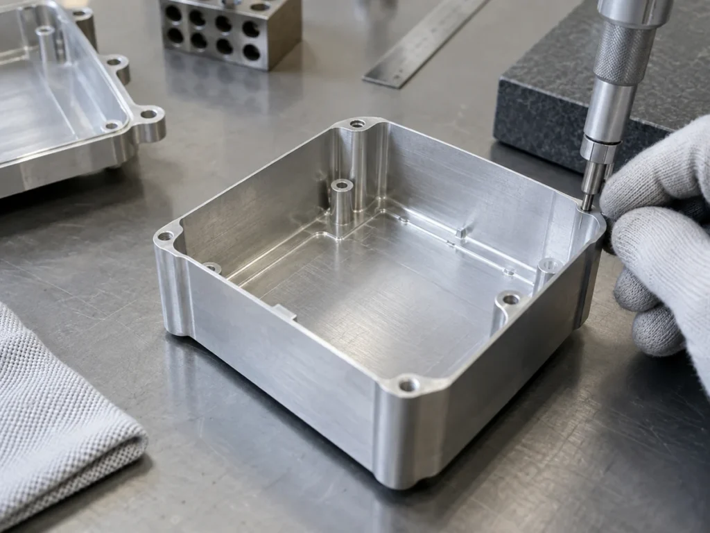
Check 1: read the drawing declaration
Look for the projection declaration or symbol in the released drawing package. Read it with the sheet title, drawing number and revision. If the information is missing, illegible or inconsistent with the views, ask the design owner to clarify it.
Do not convert the drawing by moving its views until they resemble a familiar layout. That can conceal a mismatch between annotations and geometry. The person responsible for the drawing should resolve the convention and issue the applicable definition.
ISO 5456-2 addresses orthographic representations. Its public contents list both first-angle and third-angle methods. This guide provides a reading aid; it does not reproduce the full standard or replace the drawing conventions required by your order.
When requesting clarification, be specific: identify the sheet and affected view, then ask which physical side it represents. A focused question is easier to answer than “Please confirm the drawing is correct.”
Keep labelled views readable
A separately identified view may be located away from its usual aligned position. Follow its label and direction information instead of assuming that every view near the right margin is a right-side view. Check section and detail identifiers against the features they refer to.
If a screenshot has cropped away the title block or view labels, request the complete readable sheet. Cropping can remove the information needed to interpret the remaining geometry correctly.
Check 2: identify the physical face
Agree the base view before using words such as front, back, left and right. For an unfamiliar profile, the largest face or most attractive photograph is not necessarily the designated front view.
Use a recognizable feature to orient the part: an open channel, an unequal flange or a clearly identified mounting face. Refer to features already defined by the released drawing. If you add a marked photograph for discussion, label it as supporting context and keep its relationship to the drawing clear.
For a straight extrusion, distinguish the cross-section view from views along the member. A cavity visible at the cut end is a different reference from a hole in a longitudinal wall. The drawing must make their relationship understandable.
For angled ends, identify the retained corners and the measured length. Projection arrangement does not by itself decide whether the stated length is an inside or outside dimension. Our finished-length datum guide covers that separate measurement decision.
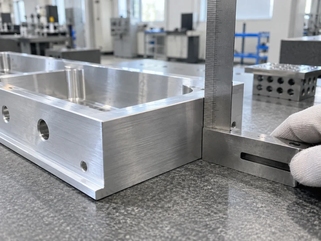
Check 3: follow an asymmetric feature
Symmetric outlines can make an incorrect interpretation look plausible. Follow a feature that distinguishes one side from the other and check its relationship across the applicable views.
Consider a fictional rail with one access opening on a specified side wall. A reviewer points to the view on the right of the front view and calls it “the right side.” That statement is correct only under the relevant view arrangement. If the drawing declares first-angle projection, the aligned right-hand view represents the left side.
The useful response is to identify the intended side wall and relate it to the declared view, rather than quietly shifting the opening to match someone’s assumption. This example describes a communication risk; it is not a reported manufacturing error or customer case.
Projection and mirrored parts are separate decisions
Changing the projection method changes the view arrangement. A mirrored part can change the physical feature locations. Do not use a change of view placement as evidence that two parts are interchangeable.
If the assembly includes handed members, check the part identities, quantities and features that distinguish them. Two items can share a similar silhouette while having different end cuts or access openings. Carry the correct identity into the cutting list and subsequent inspection.
If the visible views do not provide enough information, list the missing relationship. The design authority can supply the necessary view or clarification. Do not invent a hidden feature from symmetry alone.
Check 4: review the released package
Open the actual files supplied for the order. Compare the declared projection method, view identities and revision across the applicable sheets. A correct CAD display does not guarantee that a cropped image or an older exported PDF carries the same information.
When a model accompanies the drawing, use it to support the agreed geometry review. Do not let rotating the model into a convenient position silently redefine the front view or production requirements. State which released information governs the order.
The STEP versus PDF guide explains their different roles in an aluminum-parts quotation. File compatibility and projection interpretation are separate checks: opening the file successfully does not prove that the reviewer has interpreted each face correctly.
A short review note can record the outcome:
- The applicable drawing and revision.
- The declared projection method and selected base view.
- The identified physical face for the feature under discussion.
- Any missing or conflicting information awaiting resolution.
Use that note to close a specific uncertainty. It should not become a substitute for updating the released drawing when the definition itself needs correction.

Drawing questions buyers often ask
Does first angle vs third angle projection affect dimensions?
The method concerns view arrangement. It does not authorize changing the specified part dimensions or tolerances. Resolve how the views depict the part before using those dimensions for a manufacturing review.
Can I identify the method from the supplier’s country?
Read the drawing’s declaration. A regional habit, familiar template or software default is insufficient evidence for the particular released sheet.
Is an isometric picture enough?
It can help communicate overall shape, but it does not automatically supply the required feature definition, projection declaration or inspection references. Use the complete approved information for the requested work.
For a JiurunCut cutting discussion, send the approved profile and part drawings, with the required ends and physical reference faces identified. A shared interpretation makes the first discussion clearer and keeps later sample checks connected to the intended part.