
A plate can sit square on a saw table while its future contact face is still undefined. In battery module end plate cutting, that missing datum matters more than a persuasive photo of a clean cut. The end plate participates in a designed restraint path, but a saw supplier can only quote and test the particular blank and cut features that the product owner has released.
This is a drawing and handoff problem before it is a blade problem. The battery team must decide which surface meets the cell stack, which features locate the part, and whether the approved route even begins with an extrusion. Some end plates are forged or made by other processes; Hirschvogel’s end plate discussion is a useful reminder that material and process are design choices, not a default saw specification. No end plate or cell performance value should be inferred from a generic cutting trial.
Begin at the module’s load path
Ask the battery product owner for the released end plate drawing and module interface. Which face transfers the intended load? Where are the insulating layer, pad, band, tie rod or other restraint components? Which surfaces are protected from burrs, dents and misplaced fasteners? The answer changes what the shop measures after cutting. A length reading alone cannot establish contact pressure or module behavior.
RWTH Aachen University’s battery production overview describes module tensioning as a process controlled by the cell type, approved compression force, contact pressure and component tolerance chain. That context belongs to the module design and assembly team. The saw trial should preserve the faces and geometry that this team has specified, without pretending to validate the battery stack.
Mark one controlled datum on the cut drawing
For an approved extruded blank route, put the profile revision, alloy and condition, stock cross-section, cut length, cut-end squareness method, and designated contact or locating face on the same drawing package. Identify whether length is measured from a raw end, a faced end, or a later machined feature. Show holes, slots and joining features that are made after the saw so the supplier does not mistake a blank for a finished end plate. A PACK-line supplier’s drawing guide likewise calls for controlled locating faces, flatness, edges and joining features. Those are drawing inputs, not universal tolerances.
If the contact face is a broad surface along the extrusion rather than the saw-cut end, protect that surface during infeed, clamping, collection and packing. If the cut end itself is a mating face, agree where burr height, angularity and local damage will be inspected. Do not copy a tolerance from another module: the product owner must release the applicable limits and inspection method.
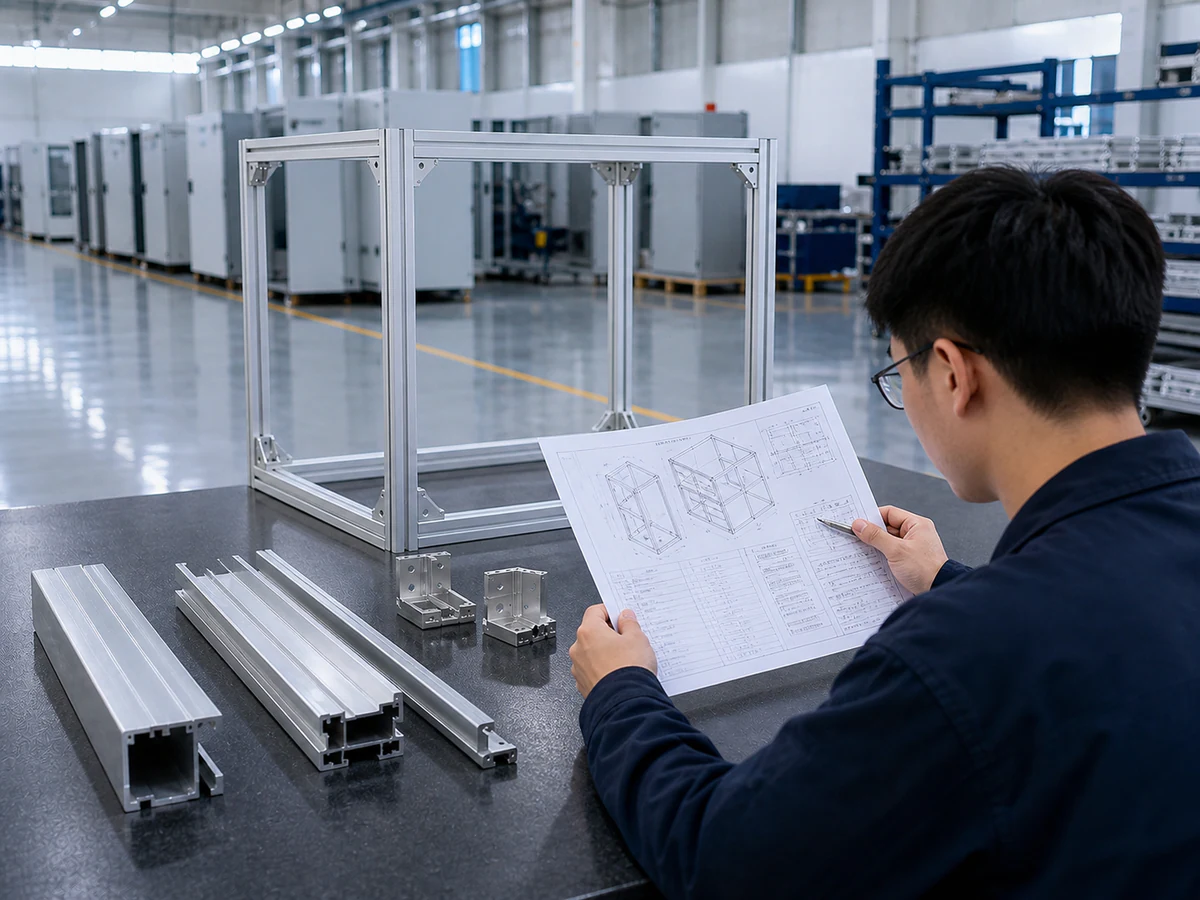
Battery module end plate cutting: support the candidate stock
A representative trial should use the approved stock shape and the proposed support and clamp contact. A thin wall, open channel or broad flat surface can respond differently to a clamp. Record the stock orientation, support span, jaw contact, protective layer if specified, and whether any visible face is scuffed or locally deformed. Measure the released dimensions on the first accepted piece and again after a short repeat run. This checks the saw process for that blank; it does not approve the end plate’s strength or compression role.
Bring the actual drawing and a representative profile to the saw supplier. If the stock is not yet released, ask for a feasibility review rather than a performance claim. Jiurun sells industrial aluminum cutting equipment; the battery tray cutting guide explains a neighboring blank-to-assembly boundary, but it does not define the end plate design here.
Keep the cut sample’s evidence narrow
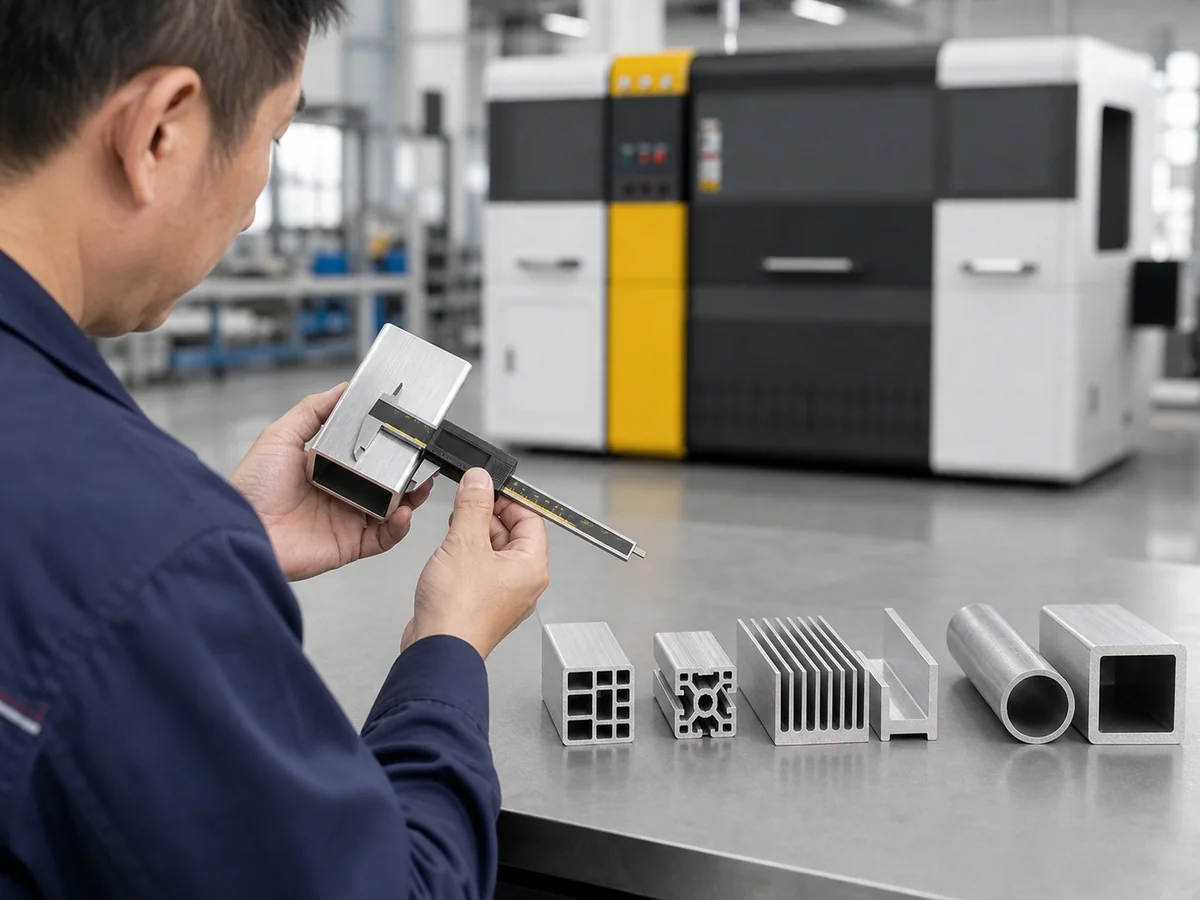
Label each sample with its stock and drawing revision, machine setup, blade, orientation, first-off status and measurement record. A caliper photo can show that a person inspected a profile; it cannot establish flatness of a broad face, force distribution across cells, or a validated module. Select the appropriate gauge and contact points from the drawing. If a later machining, coating or assembly step can alter the face, the receiving team must inspect at that later stage as well.
Release the saw blank and module separately
There are two sign-offs. The cut shop can accept or reject the defined blank against stock identity, cut length, end condition and protected surfaces. The battery team then controls subsequent machining or joining and validates the finished end plate and module under its own released criteria. If the chosen route is a forged or otherwise near-net part, the saw may have no role in making the final component. Record that decision explicitly rather than forcing an extrusion-cut quotation onto the wrong part route.
For battery module end plate cutting, a useful RFQ includes the drawing revision, stock route, candidate cross-section, batch mix, retained datum, post-cut operations, sample quantity and acceptance method. Ask the saw supplier to state what the equipment demonstration proves and what remains for the product owner. This makes the quote comparable without inventing a universal cell compression target.
Watch the saw as equipment context
The Jiurun video below shows an aluminum profile saw and its feed and cutting station. It is an equipment example only; it does not show a battery end plate, the stock in this article, a compression test or an approved module configuration.
Send JiurunCut the released blank drawing and a note identifying the protected face and post-cut route. We can review the cutting equipment against that specific stock and inspection plan.