
A machine vision camera stand may look like a simple aluminum extrusion frame, but its cut list should follow the released optical layout. A saw can produce frame members to a specified length and end condition; it cannot, by that result alone, establish the camera’s field of view, image stability or inspection performance. If you are quoting machine vision camera stand aluminum cuts, agree on the boundary between cut members, an assembled stand and an installed vision system before requesting a machine demonstration.
This guide is for an equipment builder or integrator who has selected a stationary camera arrangement and is deciding what aluminum cutting work to retain. It does not provide a camera design, a mounting approval or a promise of achieved measurement accuracy.
Freeze the camera layout before freezing extrusion lengths
Start with the target area the camera must see, its approximate working position, the lens and lighting envelope, and the access needed for focus and maintenance. Cognex’s mounting guidance says a stationary vision system should be fixed to a rigid frame, positioned outside robot travel, and given a field of view that covers the presented target. It also identifies vibration as a reason for a rigid mounting structure. Those are system-design inputs, not specifications for a Jiurun saw or proof that a particular extrusion section is stiff enough.
A buyer should therefore ask the vision integrator to release a layout showing the camera, target, light, guarded motion, cable route and adjustment range. Mark which dimensions are fixed frame-member lengths and which are finally set during installation. If the camera may move after the first optical trial, retain adjustment in the mount design instead of ordering an irreversible new cut length around an unapproved sketch.
Choose the deliverable: members, stand or working vision station
Cut aluminum members
Saw quote: released profiles, end geometry, length references, quantities, identification and cut-end condition. Next owner: the integrator assembles and aligns the stand.
Prepared frame kit
Supplier scope: cut members plus specifically ordered drilling, tapping, brackets and labeled hardware, where applicable. Next owner: the kit supplier checks completeness and the integrator checks installation.
Assembled camera stand or station
Saw quote: only the aluminum cuts actually retained in-house. Separate acceptance: the stand builder and vision integrator agree mechanical and image checks.
Do not price a complete inspection station as if it were a pile of equal-length extrusions. The camera, mount, lighting, guarding, wiring and software have separate owners. Bosch Rexroth’s FRAMEpro description illustrates the useful separation: a framing bill of materials can list strut profiles and sawing or drilling work, while connection and cap checks remain distinct design tasks. Its system is an example of documentation practice, not a claim that the pictured JiurunCut media shows a Bosch installation.
Machine vision camera stand: turn the layout into a member schedule
Give the saw supplier one row per member type, not only a perspective image of the stand. At minimum, identify the drawing revision, profile cross-section, stock condition, length datum, cut orientation, end A and end B, quantity per stand and batch quantity. Record whether the end is square, mitered or destined for another machining operation. Put connector type and the assembly reference in a separate column. A crossing in a drawing does not automatically mean two pieces must be cut at that point.
In a machine vision camera stand, uprights deserve special care: a height change may alter the camera position, but a length tolerance on the upright cannot replace final mount adjustment. Specify the physical member dimension that the saw operator can measure, then give the integrator the separate assembled-location requirement. Where a camera plate or light bracket needs holes, ask whether those holes come from an approved secondary operation; do not imply that a saw trial validates them.

Protect the optical and service envelope
Before cutting the frame, verify that the assembled stand leaves the camera lens, illuminator, focus access and cable bend path in the intended locations. A strong frame is still a poor purchase if a cross-member obscures the view or blocks maintenance. Cognex’s vision-system setup procedure describes checking the live view and then adjusting lens focus and aperture after installation. That sequence is a practical reason to keep final optical settings out of the saw acceptance certificate.
Ask who owns the stand-to-machine-base connection and whether it uses a floor mount, existing machine structure or another approved arrangement. Request the approved mechanical interface and guard-clearance drawing. Keep any stiffness, vibration and safety criteria with the system designer; a photograph of an extrusion cannot establish those properties. If a robot or conveyor moves nearby, the current layout and the project’s guarding review must govern where the stand may sit.
Run a saw trial on the members you will actually cut
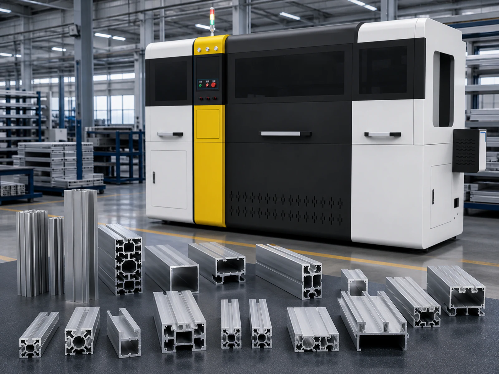
For machine selection, take representative stock from the released frame family. Include the smallest and largest cross-section, the longest retained member that must be handled, and any section whose open slot or thin wall changes clamping contact. State the real batch mix and which members are square versus angled. A trial using an easier substitute profile can help explore setup, but it should not be reported as acceptance of an untested frame family.
Agree the trial checks before cutting: correct length reference, end squareness or angle where applicable, visible burrs or deformation at the interface, surface handling, part identification and fit with the specified connector. Inspect the supported and free ends, and record any secondary deburring or machining the actual production route needs. If the buyer wants a camera stand assembled for evaluation, that is an additional system-level trial with its own acceptance owner.
Keep the cut-kit handoff separate from image acceptance
For a machine vision camera stand, the cut-kit receipt can verify part IDs, profile family, quantity, length reference, end condition and packaging. The assembled stand review can verify member orientation, connectors, mount interfaces and access. Only the installed vision review can address the actual field of view, lighting, vibration at acquisition, focus and image result. Keeping these records separate prevents a passed saw sample from being mistaken for a passed inspection system.
Consider a hypothetical stand with two uprights, a top beam, a lower brace and a separately purchased camera plate. The saw RFQ can specify four released aluminum members and their measurable ends. The plate holes, stand attachment, camera aiming and the captured-image acceptance remain with their named owners. If an optical trial changes the camera height, revise the member drawing and cut list before the next batch; do not silently change a nominal length in an old purchase order.
Send a concise, checkable RFQ
- Identify the stationary camera and target layout revision, plus the person who approves it.
- List every retained extrusion profile and exact cut member, with quantities by stand and batch.
- State length datum, end A/end B geometry, section orientation and accepted cut-end condition.
- Separate sawing from holes, threads, plates, brackets, assembly and installation.
- Show the required mount, light, cable, guard and service clearances on the current layout.
- Define representative stock for a trial and the checks that will be recorded on each sample.
- Name the owner of frame fit and the separate owner of live-image acceptance.
For broader comparison of structural fixture supply routes, see our inspection fixture frame purchasing guide. For a machine enquiry, send JiurunCut the released member schedule, actual profile samples, cut-end criteria and planned output mix through the contact page. We can then discuss a saw trial against the work your factory truly intends to retain, while your vision integrator remains responsible for the installed optical result.
References and scope
Primary technical references: Cognex stationary mounting guidance, Cognex setup procedure, and Bosch Rexroth FRAMEpro documentation. These describe general integration and documentation considerations; no third-party performance or compatibility is attributed to Jiurun machinery.
Watch a general sawing example
The following video is from Jiurun’s own YouTube channel and shows a general aluminum-profile saw operation. It is equipment context only. It does not show a machine-vision camera stand, a specific released profile, a customer project, or a verified performance trial for this article.