
Both end angles can be correct and the tube may still fail to fit if the ends face the wrong way relative to each other. Show End A and End B together, including which way each slope faces, before choosing the cutting setup.
Discuss your angled aluminum tube ends
Send a sketch of both angled ends. Mark End A and End B, and show how the tube joins the next components.
Why a round section can hide the end relationship
A plain round tube has no broad flat face that naturally identifies its top. Two pieces can have the same cross-section and the same stated angle at each end, while End B faces a different direction relative to End A around the tube axis.
Turning the whole finished piece changes where both ends point together. It leaves their relationship to each other unchanged. That relationship needs to come from the part drawing, especially when both ends must meet fixed mating surfaces.
The question here concerns the two ends of one tube. Our mirror-image part guide covers separate left- and right-hand identities. Naming a miter, bevel or compound cut describes another question: the cutting directions needed for an individual end.
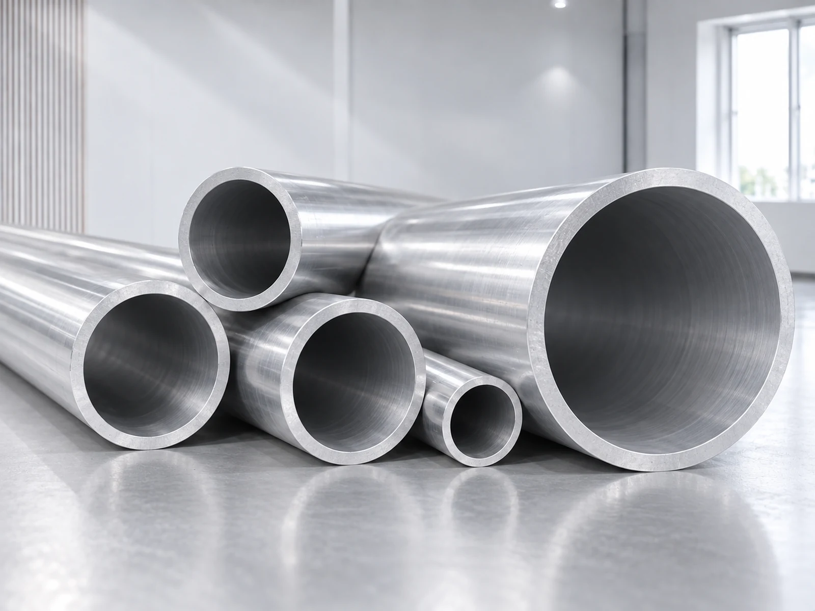
3 drawing and setup checks for angled aluminum tube ends
1. Can the supplier connect End A to End B?
Label both ends on one side or three-dimensional view of the complete tube. Add an end view for each end. Keep the labels consistent so the supplier can connect every detail to the same piece.
Show the viewing arrows. Looking from End A toward End B and looking from End B toward End A gives opposite viewpoints. A slope that appears on the left of one view cannot be compared with the left of the other without checking those directions.
Retain the drawing’s angle references, and show the required slope at each end. Ask the supplier to identify both ends on its proposed setup sketch. This makes a missing view or reversed interpretation easier to resolve before quotation.
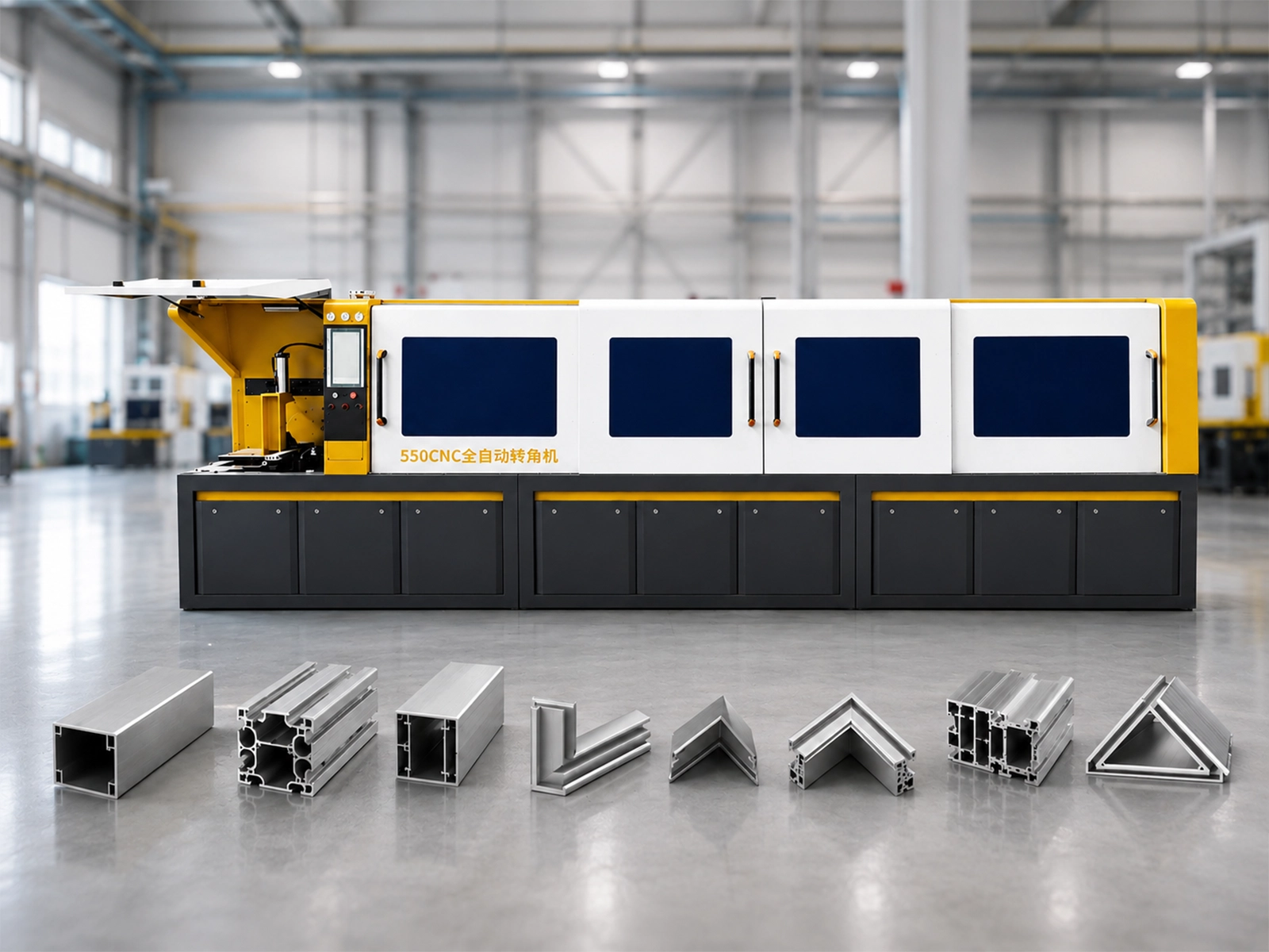
2. What reference links the two end directions?
Ask the designer to show a shared direction around the tube axis. For example, the drawing can use the long point of End A as a recognizable reference and show where the long point of End B belongs relative to it.
Carry that reference through the combined view. If the ends must face different directions around the axis, show the required relationship explicitly. Two separate angle notes may define each slope while leaving that relationship open.
Ask which feature or drawing reference the proposed setup will use to locate this direction. A circular stock outline alone does not identify it. Keep the required relationship and its acceptance limits on the approved drawing.
Have both end views ready?
Send them with a side or three-dimensional view. Point out the reference that links End A to End B.
3. How will the proposed setup preserve that relationship?
When reviewing the JR-550CNC-CORNER automatic multi-angle aluminum cutting machine, ask how the proposed arrangement keeps the required direction from the first end to the second.
Have the supplier explain how the tube is located and held for each cut. If the proposal includes a change of position or transfer, ask how the same reference remains identifiable through that step. Request an explanation tied to the equipment and approved arrangement included in the quotation.
For an agreed sample review, check both ends on the same finished tube. Ask which method will compare their relative direction with the drawing. Checking each end angle without a shared direction reference leaves the end-to-end relationship untested.
An example: one tube between two sloped mounting surfaces
Illustrative example: A factory needs a round tube to connect two mounting surfaces. Each end has an angled face, and the surfaces face different directions around the tube axis.
The buyer’s first sketch shows two end-angle notes. A combined view then reveals where each end’s long point must sit relative to the other. The buyer sends that view with the machine inquiry and asks how the proposed setup will preserve the relationship. The sample-review plan covers both mating ends together.
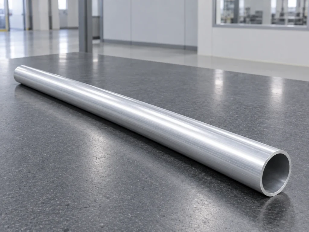
JR-550CNC Fully Automatic Angle Saw
References and the final configuration check
Autodesk’s plane-at-angle reference defines a plane relative to a chosen edge or axis. Its drawing-angle example identifies a selected view and defining lines. These support drawing clarification; the buyer checks and example are practical review guidance. Jiurun’s machinery catalog, physical PDF page 13, provides model context. Confirm the two-end requirement on the exact machine, support and clamping configuration quoted, with an agreed sample review and acceptance method.
Discuss your tube-end drawing with JiurunCut
Share both end views and their common reference. Ask how the proposed setup preserves the required end-to-end direction.