
An aluminum saw outfeed buffer is the space and handling method between a completed cut and the next operation. It matters when cutting can finish faster than an operator, rack, inspection bench, or packing station can clear parts. A buyer should define that handoff before comparing machines: an impressive cut cycle does not tell you whether accepted parts can leave the saw without a queue at the exit.
This guide is for buyers specifying a new saw or an integrated line. It treats buffer capacity as a job-specific acceptance question, not as a standard accessory or a promised throughput figure. Ask the supplier to show the proposed exit arrangement using your shortest and longest released parts, normal staffing, and downstream handling plan.
Where does the aluminum saw outfeed buffer start and end?
Draw the route from the last guarded cutting position to the first place where a finished part is positively identified and under the next process owner’s control. Mark the exit rollers or tray, any accumulation surface, the operator pickup point, and the destination rack. A roller section that supports a profile is not automatically a buffer: if the next cut must wait until that section is empty, its usable accumulation capacity may be zero for your job.
Keep three decisions separate. Outfeed support for the shortest piece asks whether a completed piece remains controlled. Part removal on a JR-650CNC loading line asks where a person or downstream device retrieves it. The buffer question asks what happens during the interval when retrieval is temporarily slower than cutting. Those can require different hardware and a different trial.
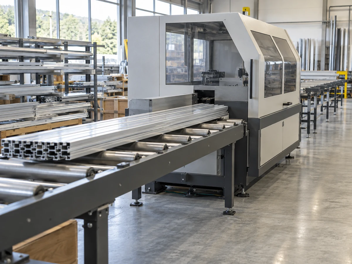
Size the buffer from a real interruption, not a catalog speed
Choose one normal downstream interruption to test: a rack exchange, a measurement check, a label change, or a short pause at the next process. Record the time from the last part removed until the receiver is ready again. Separately measure the saw’s accepted-part output during the relevant part mix. The number of pieces produced during that pause is a starting demand on the buffer, not an automatic design capacity. Leave room for the part’s actual envelope, spacing, orientation, and the safe retrieval method.
Do not multiply a single best-case cut cycle by an arbitrary delay and call the result verified. Mixed lengths, multiple profiles, offcuts, inspection holds, and a change in operator assignment alter the queue. Ask the supplier to run your released cut list and record the exit state at the moment the receiver pauses. If production must stop, define which step stops first and what conditions allow an orderly restart. If a buffer is proposed, specify its maximum accepted-part count by part family and where excess pieces go.
Check part geometry and identification at the exit
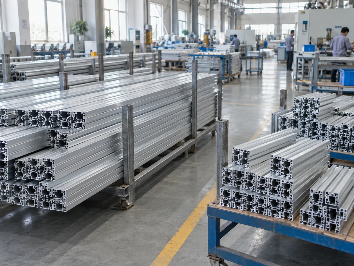
A long extrusion can bridge rollers while a short part may need a tray, chute, or dedicated catcher. Thin-wall or finished-face members may need contact protection. A mitered end or asymmetric profile can change how pieces rest and whether they rotate or snag. The buyer’s drawing, surface requirements, and released part list should determine the acceptance pieces. Include the shortest, longest, lightest, heaviest, and most damage-sensitive representative parts that the supplier agrees are within the quoted scope.
Show where good parts, offcuts, rework, and inspection holds diverge. A buffer that collects all pieces in one unmarked pile may be easy to empty but hard to reconcile with a cut list. Decide when a piece becomes a counted good part, what identifies its order or lot, and who owns the count after the handoff. If the plan uses returnable racks, define the rack transfer separately; the returnable-rack transfer checklist addresses the next boundary.
Specify the stop, access, and recovery behavior
Ask what the saw senses when an exit becomes occupied or a downstream receiver stops. The answer should describe the boundary between normal accumulation, a controlled production stop, an emergency stop, and a maintenance intervention. Confirm how the operator can see the exit, where they stand to remove accepted pieces, and whether a jam can be approached without reaching through a hazard zone. Do not assume a photo of a guard or a claim of automatic operation answers these questions.
Machine and conveyor safety depends on the actual assembly and worksite. ISO 12100 describes a risk-assessment and risk-reduction method for machinery. The OSHA machine-guarding guide discusses conveyor jams and emergency controls, while the HSE machinery introduction calls for considering normal use and blockage clearing. These references are a framework for questions, not proof that a particular Jiurun model or proposed line satisfies a local legal requirement. Have the responsible designer and site safety team assess the installed arrangement and applicable rules.
Put a safe clearing procedure and authorized personnel in the acceptance package. A jam, trapped offcut, or fallen part is not a reason to reach into a moving machine. The supplier should explain isolation, retained energy, guarding, restart permission, and how the line returns to the correct cut-list position. The buyer should witness the agreed stop and restart sequence using a safe test method, without deliberately creating a hazardous jam.
Run a handoff trial that can fail clearly
Before approving a purchase, agree a witnessed trial with a marked receiving boundary. Use representative stock and a released cut list. Run at the proposed staffing level, then pause the receiver for the agreed normal interval. Record every completed part’s location, orientation, identity, and condition; whether the saw continued or stopped; the reason for any stop; and the sequence used to resume. Repeat with the short and long parts that challenge support and pickup. If the proposed buffer cannot contain the agreed interruption, revise the layout or the operating plan before treating the quote as complete.
Define the aluminum saw outfeed buffer on a drawing or annotated layout showing the saw exit, guard boundary, buffer footprint, operator aisle, rack position, controls, and the owner of each handoff. Add the agreed part families, buffer capacity by family, normal clearing interval, and trial acceptance criteria to the RFQ. This lets competing suppliers quote the same output boundary instead of comparing only blade time or nominal feed stroke.

Related equipment footage
The video is from the Jiurun Machinery YouTube channel and shows general automatic aluminum saw equipment and feeding footage. It does not show or prove the outfeed buffer, part mix, quoted configuration, customer site, trial, safety function, or performance discussed in this article.
What to send with the RFQ
Send the released drawing and cut list, part-mix extremes, required finish, lot identification rule, downstream receiver plan, normal clearing delay, staffing assumption, and a sketch of available floor space. Ask for an exit-to-rack layout and a witnessed stop/restart and part-removal trial. For a quote against your specific job, contact JiurunCut with these inputs and request that the proposed buffer and its limits be identified in writing.