
An aluminum saw length stop is useful only when the workpiece repeatedly reaches the intended reference face. A position display, a driven axis or a quoted feed repeatability figure does not by itself show what happens when an aluminum profile touches a stop with a chip on the face, approaches it at an angle, or moves while it is clamped. Before buying a stop-based saw or adding a length-stop accessory, ask the supplier to identify the physical datum and demonstrate the released cut part against your drawing.
This guide is for a buyer evaluating a physical end stop or stop block. Some automatic saws determine length through a driven feed and encoder without using the same end-stop arrangement. Ask which architecture is actually quoted; do not assume the illustration below is the supplied machine. Keep any contact inspection within the supplier’s approved stopped, guarded setup procedure. Never reach into moving equipment to clear a chip for a demonstration.
First identify the reference that determines finished length
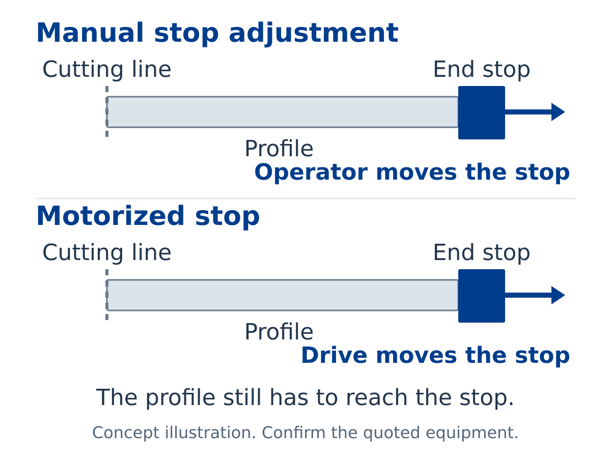
Draw the actual route from stock support to side guide, clamping area, blade and outfeed. Have the supplier mark the point that establishes the workpiece position for each cut. For a manual stop, that may be a fixed face adjusted against a scale. For a motorized stop, the carriage can set the face position, while the profile still has to make proper contact. A feed-driven system may use a different datum entirely. The quote should state which components are included, how they are adjusted and how the position is verified after a changeover.
Distinguish stop position, workpiece contact and finished-part length. They are three observations, not one specification. A display can show the commanded position without proving the profile touched the face. A profile can touch the stop yet shift under clamping. A piece can leave the saw and be measured against a different drawing datum than the one used on the machine. Ask the supplier to show the chain from requested dimension to independently checked part.
Why a chip at the contact face matters
A chip or burr between the profile and a reference face can change where the workpiece rests. The outcome depends on chip shape, contact force, profile geometry, clamping and the machine arrangement, so no universal length error can be inferred. The practical procurement question is whether the proposed setup lets the operator recognize and address an uncertain contact before parts are released. Even without visible debris, a hollow extrusion may present several possible edges to a stop; the contact point should be specified on the drawing or trial sheet.
Contact cleanliness is a general metrology principle. HEIDENHAIN notes that chip residues can affect workpiece probing with its touch probes; that is background evidence about contact measurement, not a test result for a Jiurun saw. The saw supplier must demonstrate its own arrangement with your material. Ask for a safe stopped-state view of the stop face, accessible inspection method and a documented response if a profile does not seat consistently. The supplier should determine the actual guarding and isolation procedure for the proposed machine and site. OSHA’s machine-guarding guidance is useful general safety context for US workplaces, not permission to clean or adjust a live saw.
Specify the trial stock and the contact geometry
Use a real part drawing and a stock sample representative of normal production. Record the alloy or material designation, profile cross-section, stock length, cut angle, required finished length and applicable drawing tolerance. If several profile families share the machine, choose a slender section, a hollow section or a mitered part where the contact geometry is genuinely different. State which edge or surface must meet the stop, how the stock is supported, and whether the profile is allowed to rotate or flex before clamping.
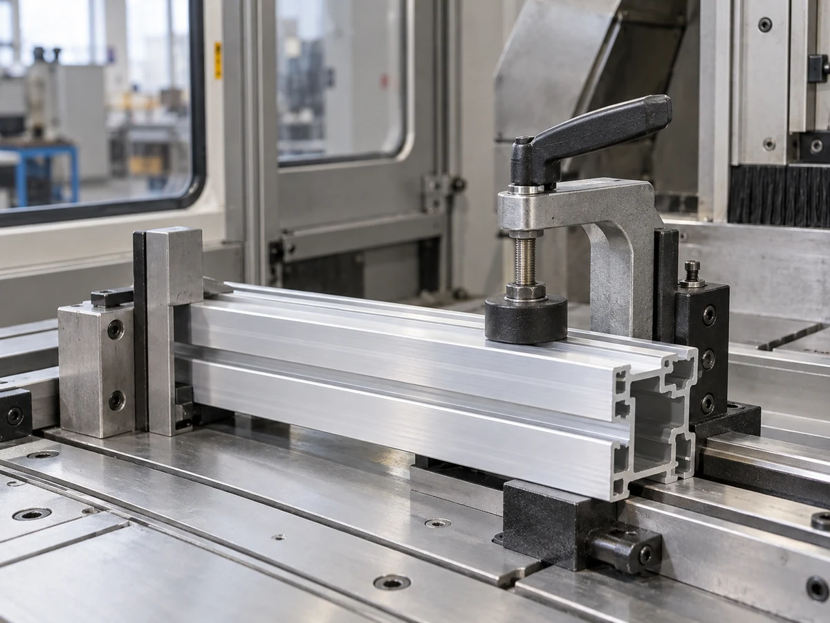
Ask the supplier to show the unloaded reference face and the seated stock at a safe stopped condition. Record whether the profile contacts a broad face, a narrow wall, an end cap or an inconsistent burr. A sliding stop block that is clear for one section can be obstructed by another. The witness should note support height, guide setting, stop face position, clamping point and any approved fixture. If the quoted machine uses feed-axis positioning instead, redirect the same trial toward its actual datum rather than insisting on a stop it does not have.
Run a safe sequence that separates causes
Agree the trial sequence before the supplier cuts. Begin with a documented clean reference condition using the approved setup method. Note the commanded stop position or feed setting, stock identity, operator, fixture and inspection method. Cut an agreed series of setup pieces and keep them physically separate from accepted production output. If the first result needs an adjustment, record the change and start a new series. The setup-cut segregation guide explains why adjustment pieces should not be quietly mixed with released parts.
For the contamination question, do not place loose chips in an active saw or defeat a guard to manufacture a failure. At a supplier-approved stopped and isolated state, ask the demonstrator to explain how routine chips are noticed, removed and prevented from affecting the next reference contact. If a safe controlled demonstration is possible, record its agreed method and observation. If it is not, list that behavior as unverified and request the design, cleaning access and maintenance instructions in the quotation. An honest unresolved item is more useful than a staged claim of tolerance.
Repeat the normal sequence after a profile changeover, after a length adjustment and after a representative production interval if time permits. Watch for the difference between a positioning problem, a contact problem and clamping movement. Do not change blade, support, stop and measuring method simultaneously; the trial then cannot identify which condition changed the output. Ask which setting the operator can check during a shift and which requires trained maintenance.
Measure released parts with an agreed datum
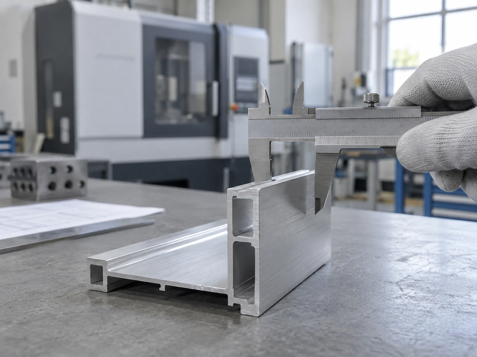
Remove each sample through the normal safe process and inspect it in the free or supported state specified by the drawing. Identify the measurement points before measuring. A mitered end, burr, radiused corner or open extrusion wall can make a caliper reading ambiguous. Choose the instrument and method appropriate to the tolerance and geometry, and note its identification and calibration status where required by the buyer’s quality system. Mitutoyo advises cleaning caliper measuring surfaces before use; this supports sound measurement practice, not a claim that any particular saw meets a tolerance.
Link every result to its stock bar, setup state and cut order. A useful trial sheet contains requested length, measured length, measurement datum, profile orientation, stop or feed setting, whether the piece was an adjustment cut, and the disposition. Record any refusal to seat, manual intervention or unusual chip accumulation beside the affected piece. Do not substitute a feed repeatability number for finished-part accuracy. Compare results with the actual drawing tolerance only after the parties agree that the measurement method is suitable. For outsourced parts, the datum and measurement agreement addresses how the same question can later become a supplier dispute.
Compare quotations by the complete contact route
Ask each supplier for a drawing or photograph identifying the proposed datum, stop face or feed reference, side guide, clamp, guard, chip path and safe inspection access. Require the adjustment range and included accessories in writing. If one offer relies on a manually moved stop and another on a driven stop, compare changeover work, verification method and operator access alongside purchase price. A more elaborate axis does not remove the need for reliable workpiece contact when a physical stop remains part of the route.
Agree who supplies trial stock, what constitutes a representative sample, how many cuts are required for your decision and how nonconforming or uncertain pieces are handled. State whether a chip-management accessory, air system or special stop face is standard, optional or excluded; do not infer that a catalog photograph proves inclusion. Ask for the actual machine manual and risk assessment information needed by your site before promising a cleaning interval. If the seller recommends a different feed architecture, have them explain how it establishes the datum and provide the same finished-part evidence.
Related equipment video
The following video from the Jiurun Machinery channel shows general automatic aluminum saw and feeding movement. It is equipment context only. It does not show this article’s stop-contact trial, chip condition, quoted configuration, customer or length performance.
Questions to settle before purchase
Does every aluminum saw need a physical length stop?
No. The proposed machine may use a physical end stop, a driven feed system or another positioning arrangement. The supplier should identify the real datum before you design a trial.
Can a chip at the stop be converted into a universal error allowance?
No. Geometry and contact conditions vary. Test representative material safely and measure the released parts against the agreed drawing instead of applying an assumed correction.
What if the supplier cannot demonstrate the contact condition safely?
Keep that item open. Request the design and approved stopped-state inspection procedure, then arrange a safe witnessed test or a written acceptance condition before order release. Never trade guarding for a dramatic demonstration.
Send a useful RFQ
Send the profile drawing, stock dimensions and material, cut angle, finished-length requirement, expected changeover mix, production environment and proposed acceptance method. Ask the supplier to identify the offered datum and return a witnessed cut-part record for representative stock. Contact JiurunCut with these inputs to discuss a suitable aluminum saw configuration and the trial evidence needed for your purchase decision.
Sources for the general contact and safety principles: HEIDENHAIN TS 460 workpiece probing; Mitutoyo measuring-instrument checkpoints; OSHA machine-guarding overview. These sources do not verify a specific Jiurun model or trial result.