
Manual vs pneumatic saw clamping is a purchase decision about the whole cutting sequence, not a contest between two clamp labels. The same aluminum profile can behave differently when the contact point, locating face, operator sequence, or air-loss response changes. Before choosing an arrangement, ask the supplier to demonstrate each proposed option on your released section and finished-part drawing, with the same stock and acceptance rules.
This guide is for buyers comparing a manually operated toggle or screw hold-down with a powered pneumatic hold-down in an industrial aluminum saw proposal. It does not claim that every JiurunCut model has either arrangement as standard. The quoted machine, approved tooling and safety controls must be identified for your job.
Define the job before comparing clamp types
Send the profile cross-section, stock length range, finished lengths, cut angles, wall thickness, material/temper callout and drawing revision. Mark the surface used as a locating reference, the faces that may be contacted, and any visible, sealing or assembly faces that need protection. If several profiles share a machine, list each family and expected batch pattern. A comparison made with one easy, thick section may tell you little about a thin or asymmetric member in the same order mix.
Ask the supplier to show the cutting-capacity fit and the proposed stock path separately from the clamp layout. A profile fitting within the saw envelope does not establish an acceptable way to locate and restrain it. The earlier aluminum saw clamping checklist explains the broader drawing and quote scope; the decision here is whether manual actuation or a pneumatic hold-down gives your specific production route the better accepted output and operating arrangement.
Keep the datum and contact map constant
A locating stop establishes where the workpiece sits. A hold-down restrains it during the cycle. Those jobs should be identified separately on a marked section drawing. Compare manual and pneumatic options against the same intended orientation, locating face and protected surfaces. Otherwise, a better-looking cut may result from a different datum or support scheme rather than the actuation method.
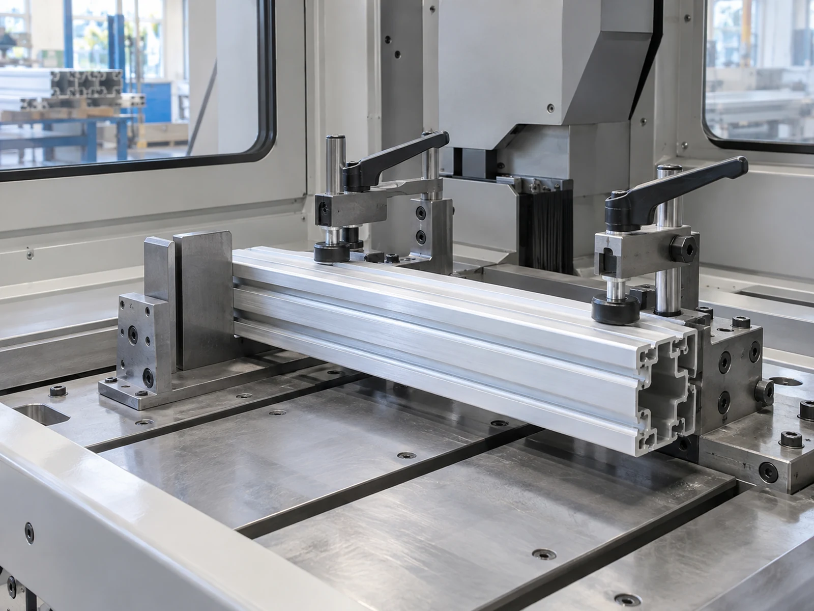
For each option, request a simple contact map: stop faces, upper and side contacts, support points, contact material, adjustability and any special nest or pad. Ask who signs off the setup for a new profile revision. A pneumatic actuator does not remove the need to control the contact surface, and a manually locked clamp does not guarantee that two operators will apply the same pressure.
What manual clamping can suit
A manual toggle or screw hold-down may be reasonable when production is staffed, batches are short, profile families change often, and the operator has a clear, safe reach to the clamp. The buyer still needs to test the complete cycle: place stock, locate it, close every clamp, confirm the ready state, cut, release, remove the part and prepare the next piece. Time only the clamp stroke and the comparison will miss loading and part removal.
Check access with the longest and shortest intended stock, and with the actual guard and enclosure in place. Can the operator reach the handle without leaning over a hazardous zone? Can the clamp open far enough for the tallest section? Does its arm or spindle obstruct a blade path, feed movement or finished-part removal? These are layout questions for the specific machine; a catalog holding-capacity figure is not a substitute for a supplier-approved fixture review.
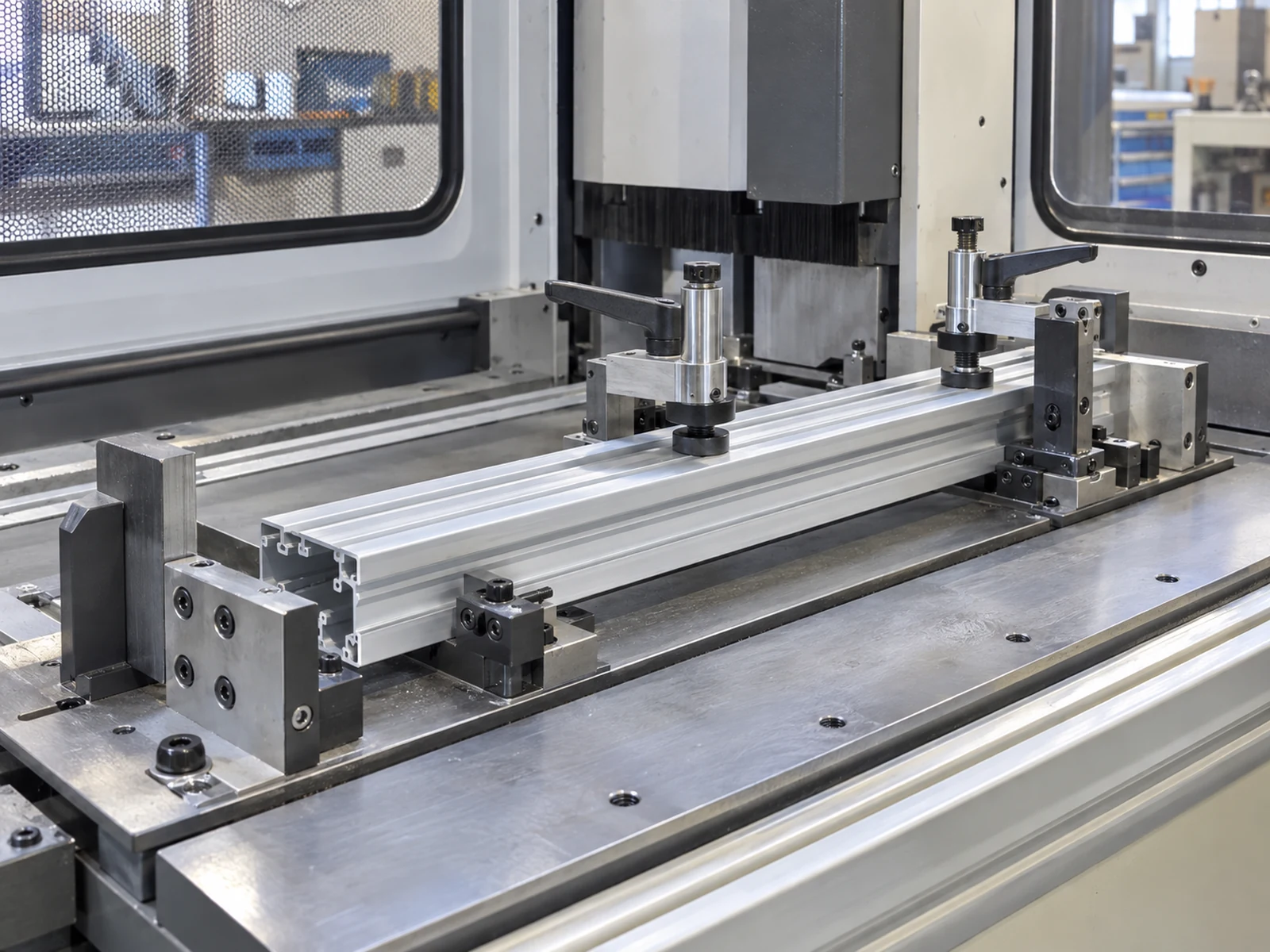
Manual toggle-clamp supplier DESTACO distinguishes clamping force from holding capacity and notes that the force a person applies depends on how the handle is operated. Treat that distinction as a question to ask the saw supplier: what contact force or setup method is approved for this profile, and how will operators repeat it? Do not copy a component rating into a claim about finished-part accuracy.
What pneumatic clamping can change
A pneumatic hold-down can remove a manual handle movement from each cycle and can be sequenced with a control system. That may matter when the same profile is cut repeatedly or the operator must coordinate several contact points. It also adds a compressed-air circuit, valves, cylinders, controls, maintenance items and a behavior to define when supply pressure falls. Do not assume the machine becomes fully automatic: stock loading, feeding, cutting and discharge are separate functions.
Ask the supplier to identify the actual actuator and circuit included in the proposed machine, the regulated operating conditions, the contact pads and the control sequence. Which signal confirms the clamp is in the intended state before cutting? What happens if the workpiece is missing or positioned incorrectly? How is pressure reduction, power loss or a stopped cycle handled, and who authorizes restart? The answer may depend on the selected circuit and any mechanical lock; the word “pneumatic” alone does not define a safe state.
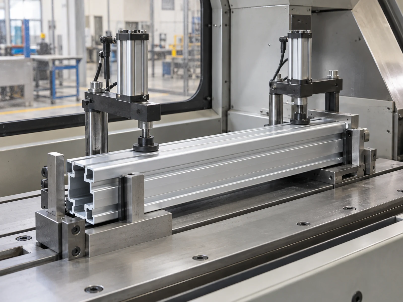
SMC’s pneumatic-cylinder operating guidance warns that a pressure reduction can reduce clamping force and calls for safety measures in the application. This is a component-level caution, not a statement about any specific JiurunCut circuit. Require the machine supplier to document and demonstrate the actual installed response, including workpiece disposition and deliberate restart. Our air-loss recovery buying guide covers that wider handover.
Manual vs pneumatic saw clamping: run one representative comparison
Agree an acceptance matrix before the trial. Use the same released drawing, material lot or agreed equivalent, profile orientation, blade specification and finished-part inspection method for both options. Record any change in support or fixture so the result is not mistakenly attributed to actuation. Include the smallest and largest relevant sections, and at least one thin-wall or surface-critical family if those are part of the purchase.
Ask for a complete sequence on each profile family: setup and first-piece approval; a representative production run; a change to another profile; and restart of the first family. Record accepted parts, rejects and their reasons, contact marks, profile movement, burr or cut-end findings, operator interventions and the time from stock presentation to accepted-part handoff. A faster clamp stroke is useful only if the full route produces the intended accepted output.
Finished-length and angle checks should use the drawing’s datum and agreed measurement method. A servo feed repeatability statement, if offered, is not itself a finished-part tolerance result. If a sample fails, record whether the source was location, restraint, blade/cut conditions, measurement or downstream handling before changing the clamp specification.
Compare total quote scope and service work
Request two written configurations or a clearly priced option sheet. For the manual version, identify the clamp model or type, special arms or pads, setup aids, guarding assumptions and replacement parts. For the pneumatic version, identify the cylinders, valves, regulator or air preparation, sensors if proposed, control logic, required site air service, spare seals/pads and maintenance access. Ask whether the supplier will commission and validate each arrangement on the submitted profile families.
Compare purchase price only after those inclusions are aligned. A lower initial fixture price can be offset by a labor-intensive cycle, but a powered option can add installation and maintenance work. Neither outcome is universal. Use your real batch size, changeover frequency, accepted output and local air provision to calculate the business case. If the supplier proposes one arrangement only, ask them to state the reason and the acceptance evidence, not to invent an unsupported comparison.
Decision sheet for the RFQ
- Part family: drawing revision, stock condition, orientation and protected faces.
- Contact plan: locating faces, support points, hold-down pads and approved force/setup method.
- Operator route: reach, guard state, loading, clamp/release, cut and removal.
- Powered route, if proposed: air service, control sequence, confirmation signal, loss-of-air behavior and restart.
- Trial: same representative parts, measurement method, accepted-count definition and changeover run for each option.
- Quote: included tooling, options, spares, installation responsibility, training and exclusions.
If the manual vs pneumatic saw clamping evidence favors a manual fixture for one short-run family and powered restraint for a repeat family, ask whether a single machine can support both approved setups and what changeover would require. Do not assume interchangeability from similar photographs. The useful output of the review is a written configuration and trial acceptance plan, not a blanket claim that one technology is always faster or more accurate.
Video: general equipment example
The Jiurun Machinery channel video below shows general cutting equipment and a clamp area. It is included only to illustrate equipment layout. It does not demonstrate the profile, manual/pneumatic comparison, quoted model configuration, customer, sample trial, force, cycle time or cut quality discussed in this article.
Ask for a decision-ready proposal
Send your profile section and finished-part drawing, target batch pattern and proposed air supply to JiurunCut’s engineering contact page. Request a contact map and a representative acceptance trial for the exact quoted clamp arrangement. That gives purchasing, production and maintenance teams one basis for deciding whether manual or pneumatic restraint belongs in the order.