
A rail can leave the saw at the specified length and still lose a roller-shaft holder from its open end during assembly. In a slotted roller conveyor, the end of the extrusion may be the insertion route for the holder and also the place where a separate stop must be installed. Aluminum roller conveyor rail cutting therefore needs a decision about end access and retention before a buyer releases a simple length schedule.
This is a guide to specifying cut aluminum members for a particular roller-track system. It does not claim that every conveyor uses slot-in holders. The system owner must confirm the actual rail, roller, shaft, holder and end-stop design. The saw supplier can demonstrate the blank and its cut end; the complete conveyor requires its own assembly and functional approval.
Before aluminum roller conveyor rail cutting, identify the retention method
Ask for the approved rail section and holder or shaft detail, not just a photograph of a conveyor side rail. Some systems insert a separate holder into an extrusion slot. Other systems support shafts through holes in a side profile, or use a purchased track assembly. These architectures put different requirements at a saw-cut end. A cut length that is suitable for one cannot automatically be transferred to the other.
MISUMI’s conveyor roller shaft-holder catalog example shows holders inserted into an extrusion slot. Its illustration also says that a lock nut or another extrusion at the edge prevents the holder from falling out. That is a product-family example, not a universal stop design or a specification for JiurunCut equipment. It makes the buyer’s question concrete: what physically closes the holder’s escape path after this rail is cut?
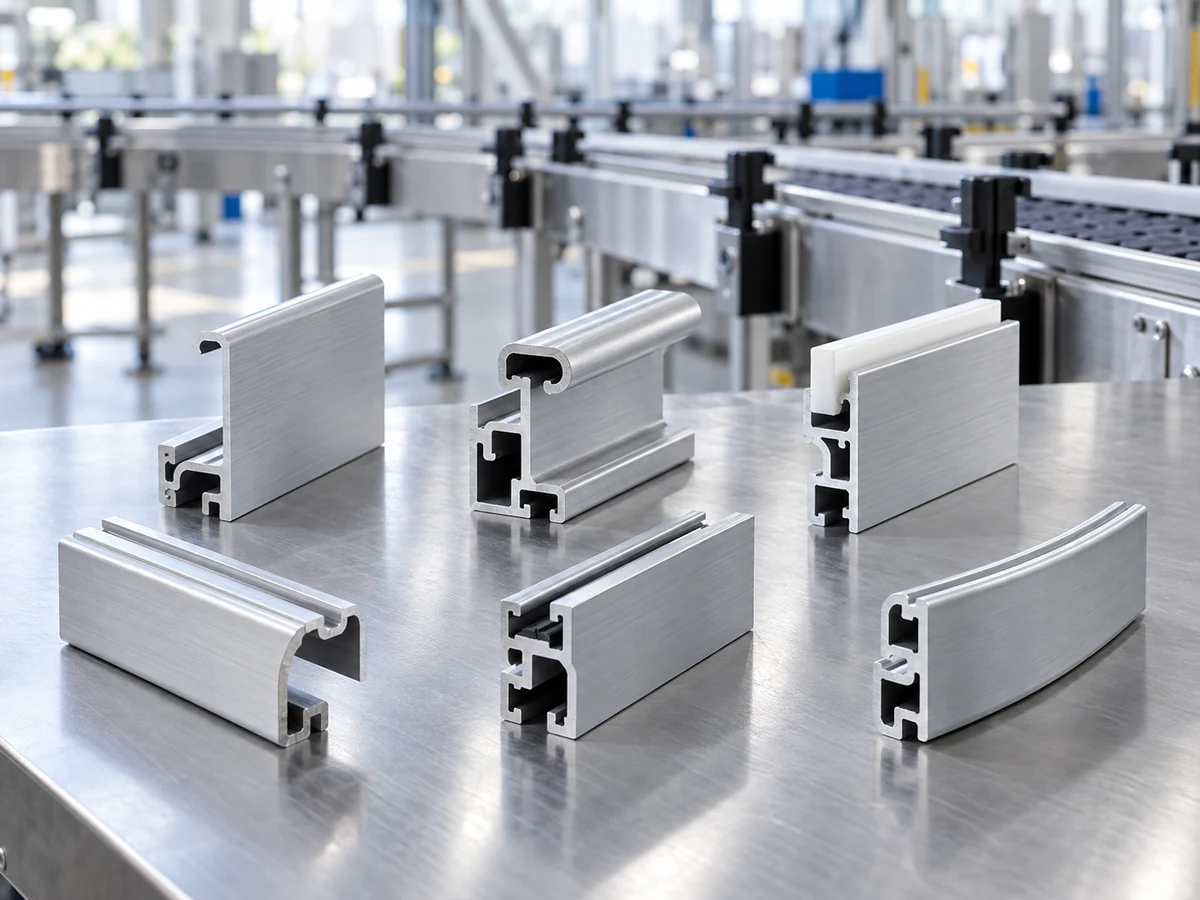
Draw the end as an assembly interface
On the released drawing, mark the working slot, the rail’s orientation, the end from which holders are inserted and the final position of the first holder. Then mark the end-stop component and its required installation space. If another frame member closes the slot, identify that member and the assembly sequence. A long rail cut into two shorter pieces creates two new ends; each finished piece needs its own retention decision.
Separate three dimensions that are easy to mix. The saw blank length is measured between defined end references. The usable roller span depends on the installed holders and their pitch. The end-stop clearance belongs to the assembled system. A nominally correct blank from aluminum roller conveyor rail cutting does not establish either roller pitch or retention. Do not subtract a generic allowance from every rail; use the approved holder and stop geometry for this build.
For a rail whose end is later drilled, tapped or machined for a stop, specify whether the saw is supplying a blank for that later operation or a finished ready-to-assemble member. The cutting shop should not imply that it has completed the fastening feature by leaving a clean cut face. Conversely, if the stop is a separate post-assembly nut, record who supplies and installs it. This prevents a saw purchase order from silently becoming a conveyor-assembly promise.
Keep the insertion path open without assuming the slot fits
Before choosing a cutting setup, locate the slot and any thin lips near the cut. The trial sample should show whether the actual holder can enter by the approved route after cutting and any specified edge finishing. A clean photograph of the end is useful for location, but a physical holder-fit check is stronger evidence for this interface. Record which face was contacted during the check and whether the holder moved to the intended position.
Examine the cut-end condition that matters to that holder: burrs or displaced lips at the slot mouth, an end face that interferes with the stop, and an orientation error that changes the first-holder spacing. The applicable acceptance method and limits come from the system drawing and holder supplier. The saw operator should not alter a safety guard or improvise access to reach a short part; any setup or finishing change belongs to the responsible trained team under the machine instructions.
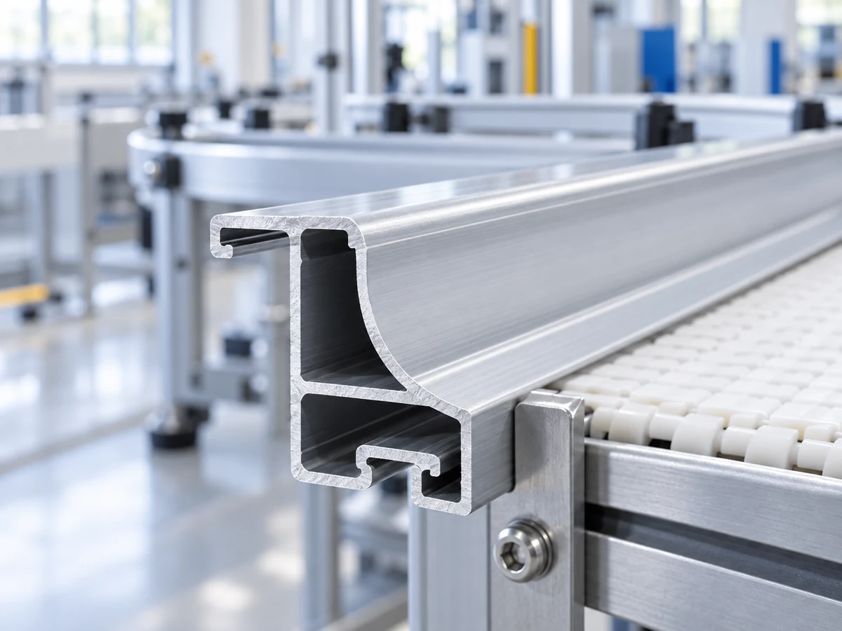
The T-slot image below is a related open-ended extrusion, useful for pointing to lips and slot entrances. It is not the roller conveyor rail in the MISUMI example. Its shape cannot establish the fit of any holder on your project.

Use one assembled witness, then define the production boundary
For an aluminum roller conveyor rail cutting trial, provide representative extrusion stock, the approved cut length and datum, and one actual holder and end-stop set where practical. Label the retained end and the insertion end. Ask the saw supplier to return the cut blank with its measured length and specified edge observations. The system owner can then assemble one witness: insert the holder, place a roller, install the end stop, and check the required position and retention under the approved method.
A witness that fails should keep its evidence. A holder that will not enter may indicate a slot-mouth condition, but it might also be the wrong holder or extrusion revision. A holder that slides out may indicate a missing stop, an incomplete assembly sequence, or a different retention architecture. Do not assign every failure to the saw. Record the cause review and rerun only the relevant stage after an authorized change.
Make the purchase decision explicit. If the supplier is selling cut blanks, the quote should state the rail identity, cut reference, length range, allowed end condition, sample evidence and pack identification. If the supplier is selling a complete roller rail, the quote needs the holder, shaft, roller, stop, assembly and system test scope as separate agreed items. The general conveyor side-rail drawing guide covers orientation and brackets; this guide addresses the holder’s open-end escape path.
The Jiurun Machinery video below shows a related aluminum profile feeding and cutting operation. It can help a buyer discuss how a proposed rail would be presented to a saw. It does not show the roller holders, the end-stop installation, the specific extrusion in this guide or a completed conveyor trial.
To discuss a cutting trial with JiurunCut, send the released rail drawing and a representative extrusion, together with the holder and stop details that determine end access. Ask which cut-blank evidence a proposed machine configuration can produce. The conveyor designer and assembler remain responsible for proving that the retained rollers work in the completed system.