
Aluminum louver blade cutting starts with identifying the exact member being supplied. A façade order can include blades, supports, frame sections and end fittings. Each needs its own drawing reference and finished-part definition.
The useful purchasing question is simple: will the delivered cut members fit the approved assembly in the intended orientation? Build the cutting enquiry around that question before comparing saw configurations or batch quotations.
On this page
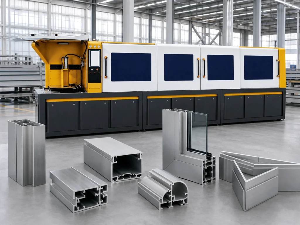
Aluminum louver blade cutting: separate the member families
Architectural systems do not all use the same arrangement. Renson’s fixed brise-soleil overview describes horizontal and vertical configurations, including aluminum blades carried by a façade support structure.
Its Linius horizontal-cladding overview describes multiple blade types, modular construction and tailored assemblies. These are examples of why the part list must follow the selected architectural system.
A sun-shading blade, a ventilation-louver blade and a decorative screening member may have different sections and connections. Establish the intended system with the designer. Do not infer airflow, rain resistance or shading performance from a cut-member photograph.
Give every family a clear identity in the order: blade profile, perimeter frame, intermediate support and separate fitting. Keep purchased end caps or clips outside the saw-cut member count unless the approved schedule explicitly includes them.
1. Confirm drawing identity before requesting a cutting quote
For each member, provide the profile drawing number, revision and material specification approved for the project. Include a cross-section that identifies the surfaces used for support and the features that must remain clear.
Names such as “louver extrusion” are too broad for a machine review. The supplier needs the actual section, stock condition and range of required cuts. A hollow section and an open shaped section can present different contact and support questions.
Where multiple blade variants look similar, assign separate part codes. Keep the code on the drawing, cut list and packaging label. This helps the buyer distinguish a wrong profile selection from a length or angle issue.
The general cutting-machine RFQ checklist covers the wider machine enquiry. For this application, add the assembled-screen drawing so the supplier can understand how each member is used.
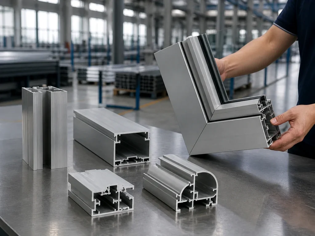
2. Define the finished length and the end connection
State which two features define the finished blade length. Is the dimension between cut ends, connection shoulders or another drawing-defined reference? Show the answer on the part drawing.
Then identify what happens at each end. An end cap, clip, bracket or frame pocket may affect the part definition. Let the approved design specify any clearance or engagement requirement; do not create a universal deduction from the façade opening.
Distinguish a square-ended member from an angled end. For an asymmetric section, an angle instruction also needs a defined orientation. A saw angle on its own does not show which edge establishes the finished dimension.
Include the drawing tolerance and the agreed inspection method. Where the datum is unclear, use the finished-length datum guide to prepare the question for the designer. Resolve it before releasing the production cut list.
3. Keep installed direction and finish requirements clear
Mark the exposed face and the installed direction on the section view. Also identify left-hand and right-hand variants where the design calls for them. A correct length can still belong to the wrong member orientation.
Ask the cutting supplier to review contact locations with the actual section. Support and clamping should be discussed against the profile geometry and the approved machine instructions, especially where a visible face or slender edge is involved.
State whether stock arrives finished or is coated after cutting. Include the agreed surface condition, handling method and any separate finish operations. The coating specification belongs to the project and finishing supplier; it cannot be inferred from an aluminum sample’s appearance.
If a visible-face concern remains, include a representative sample and the agreed assessment conditions. Record the decision alongside the member code rather than relying on an informal photograph exchange.
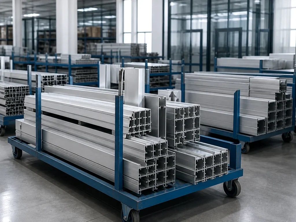
4. Release one coordinated member schedule
A useful aluminum louver blade cutting schedule links each part to its assembly location. Keep the drawing revision, finished dimension, end condition, orientation and quantity on the same controlled record.
| Member record | What the buyer should resolve |
|---|---|
| Blade section and location | Which profile, revision and installed direction apply to this member? |
| Length and end connection | Which features define the dimension, and what fitting or pocket receives each end? |
| Finish and release status | Which surfaces need protection, and which drawing version is approved for cutting? |
This is an editorial record structure. It does not specify architectural loads, blade spacing, airflow or a universal assembly allowance.
Have the responsible designer approve the member definition. Agree a sample or first-part review with the supplier where appropriate, then retain the accepted record. Keep any later drawing change tied to the affected members and remaining quantities.
Send JiurunCut the profile sections and member schedule to discuss the cutting arrangement. Include the intended batch mix and stock lengths. Machine suitability should be reviewed against those actual inputs.
Questions buyers ask
Can the overall façade width be used as the blade cut length?
Only if the approved drawing defines it that way. End connections and drawing datums may make the part dimension different.
Are all aluminum louver blades interchangeable?
No. Confirm the section, connection and approved system before treating two blade descriptions as equivalent.
Does a square cut confirm the assembled louver’s performance?
No. Cutting geometry is one input. Architectural performance requires the design and evidence for the complete system.
What should accompany an aluminum louver blade cutting enquiry?
Send the section and assembly drawings, controlled member schedule, stock condition, finish requirements and agreed acceptance references.