
Aluminum linear rail mounting needs more than a cut-to-length profile. Define the supporting member, the prepared rail seat, the mounting-hole pattern and the final assembly checks. The aluminum support and the linear guide are different components with different acceptance requirements.
Start the RFQ from the selected guide’s current mounting documents and the released support drawing. A rail that fits the available slot or overall length is not automatically approved for the required motion accuracy.
On this page
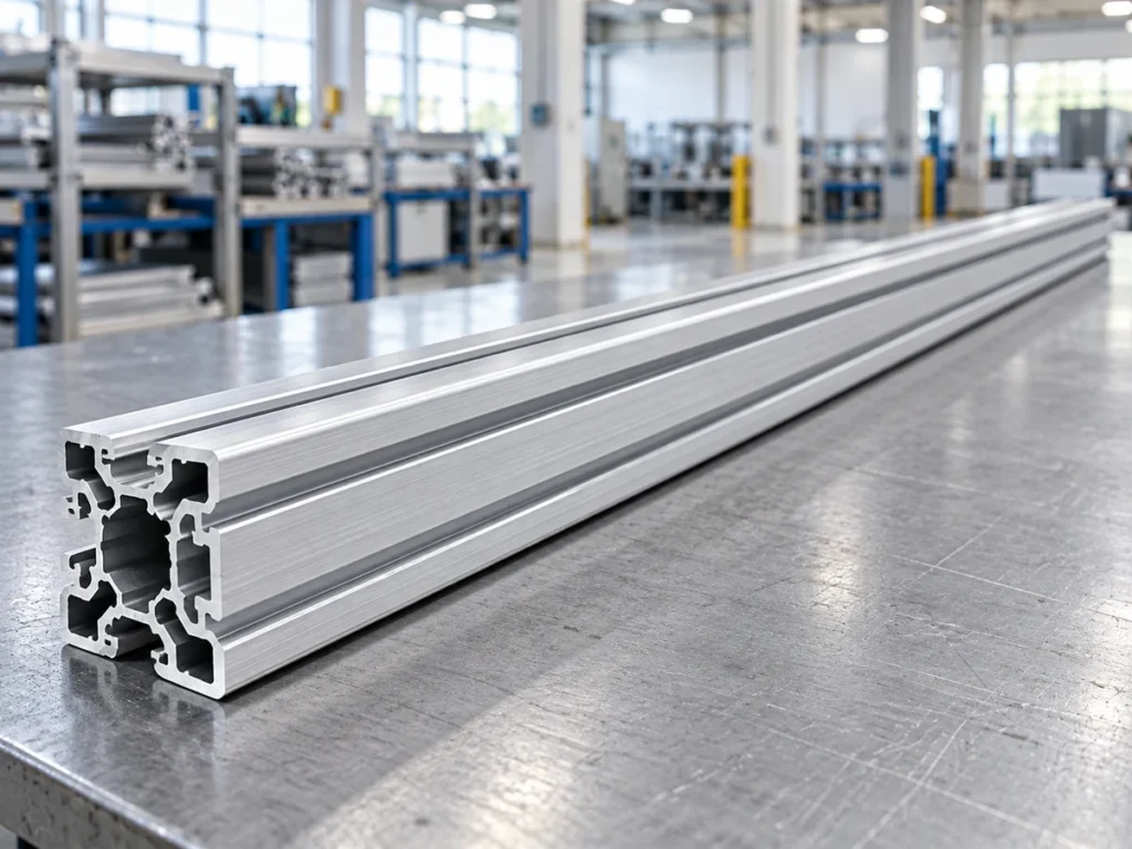
1. Define the scope for aluminum linear rail mounting
Separate three identities in the part list: the aluminum support, the guide rail and the moving bearing block or carriage. Add any adapter plate or connection hardware as its own item.
For the support, specify the profile reference, material condition, cut length and required secondary work. For the guide, keep the exact manufacturer and product designation connected to its mounting information. Do not use the support’s profile number as a substitute for the guide identity.
The quotation should state what arrives at the buyer’s site. A raw cut member may need machining and cleaning before assembly. A machined support should have an identified drawing and report. An assembled axis requires additional checks of the integrated system.
Thomson’s guide-rail information explains that mounting conditions can impose deflection on profile rail bearings, affecting friction and precision. This is a reason to review the support interface; it is not a numerical capability claim for any aluminum profile.
Keep length and travel separate
The cut length of the support is not the usable travel of the completed axis. The assembly drawing must account for the actual guide, carriage, end features and surrounding interfaces. Ask the designer to state the required travel and envelope separately from the member’s finished length.
2. Define the rail seat and reference surfaces
Identify the surface that supports the rail and any edge used to locate it. State whether these areas remain as supplied or require machining. The supplier should be able to point to the controlled surfaces on the drawing.
A general requirement for a straight profile does not define every feature of a guide mounting seat. Separate the member’s overall straightness from the local mounting-face and reference-edge requirements selected for the assembly.
Obtain the limits from the responsible designer and the documentation for the actual guide. Do not apply one flatness or alignment value to every rail size, accuracy class or support arrangement.
The HIWIN linear guideway assembly manual identifies rail reference sides and discusses different rail fixing arrangements. It also requires clean mounting surfaces and burr-free mounting holes and edges. Refer to the instructions for the selected product; a generic sketch is not a complete installation plan.
Our stock-straightness guide can support the incoming-member review. Keep that check separate from any machining or assembly acceptance required for the rail seat.
3. Coordinate holes, fasteners and end references
Build the hole pattern from a defined datum end and the released drawing. Confirm which end is used for the first hole and how the part is oriented in the assembly. Reversing a profile can preserve its overall length while moving the hole pattern to the wrong position.
Distinguish through holes, tapped holes and any head-clearance features. Record their identities and the required preparation rather than describing the whole pattern as “rail holes.”
Ask the designer to identify the approved fastener and engagement requirements for the actual support. The available wall or slot geometry matters to that review. A compatible-looking bolt diameter does not establish the complete connection.
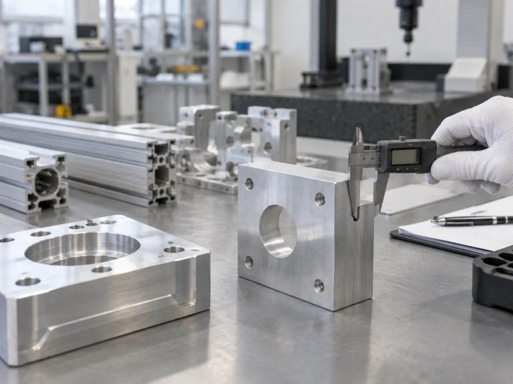
Preserve orientation through production
Label the datum end and controlled face using the agreed part-identification method. If multiple supports are handed or paired, keep their assembly identities visible through cutting, machining and packing.
Use the hole-position drawing guide to structure the dimensional requirements. The guide manufacturer and system designer still define the actual installation interfaces and limits.
4. Specify what is delivered to the assembler
Describe the delivery stage in practical terms: cut and identified, machined to the support drawing, or assembled with specified components. Include the required edge condition and any retained surfaces.
For a machined support, agree how the rail seat and holes are protected during storage and transport. Keep chips, packaging contact and identification marks out of controlled areas where the released requirement calls for that protection.
If a finish is applied, show whether the mounting surfaces and holes are affected by it. The design should specify the finished interface condition. The supplier should flag a conflict between the finish order and the guide-seat drawing before processing.
Do not assume that a clean-looking profile is ready for mounting. Incoming inspection should check the actual delivery requirements and report any contamination, burrs or damage requiring disposition.
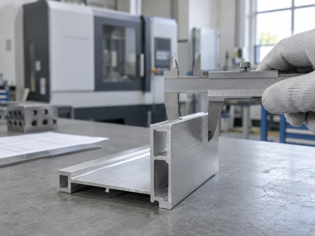
5. Assign the checks at each assembly stage
Use a simple handoff plan so that the cut supplier, machining supplier and assembler know what each report covers.
- Cut member: verify identity, material reference, finished length, orientation and specified end condition.
- Prepared support: inspect the released mounting surfaces and hole features using the agreed method.
- Installed guide: perform the product-specific alignment and assembly checks defined by the responsible team.
- Completed axis: evaluate the required motion and system behavior against its own acceptance plan.
A support dimensional report should not be described as proof of axis positioning accuracy. Likewise, the guide’s catalog accuracy does not establish the result of the completed installation.
Where a report covers a pair of supports or rails, identify both items and their intended arrangement. Avoid records that name only a general profile size while omitting the part number or assembly revision.
Handle a supplier change explicitly
If the supplier proposes a different profile, adapter or fastening arrangement, ask for a revised component list and affected drawing requirements. The responsible designer should review the change before production. Record the approval so it can be followed on repeat orders.
These reviews belong in the first-article inspection record when applicable to the order. Keep proposed changes separate from measured results.
Buyer questions
Can a standard T-slot profile carry a linear guide?
Suitability depends on the selected guide, support design and required system performance. Ask the responsible designer to define the mounting seat, fastening and verification plan. Slot compatibility alone does not approve the assembly.
Does cutting accuracy determine positioning accuracy?
No. Cut length is one part requirement. Positioning behavior belongs to the completed motion system and depends on its approved components, installation and verification. Keep the two acceptance records separate.
Should I machine the profile’s top surface?
Use the released design and guide mounting requirements to decide. A supplier should quote the specified surface condition and identify any proposed change. Do not order machining solely because a surface looks uneven in a photograph.
Can one caliper measurement approve the mounting seat?
No. A local dimension check does not establish surface flatness or reference-edge straightness. Agree the inspection method for each controlled feature and retain the results with the identified support.
Prepare the support-member cutting review
Provide the profile section, material reference, required length, datum end, batch quantity and secondary-operation drawing. State whether the order stops at a cut member or includes further preparation.
Contact JiurunCut with representative aluminum support drawings to discuss the cutting stage. Keep guide selection, support machining, assembly and completed-axis validation responsibilities explicit in the project scope.