
Aluminum extrusion tongue ratio helps the extrusion supplier review a narrow opening and the die feature needed to form its adjoining space. Identify the relevant void area and gap or supporting-base width on the actual section. Keep the supplier’s definition with the calculation.
A profile can look simple in a thumbnail while a narrow opening creates an important tooling discussion. The useful next step is a section review with the extruder, using the full geometry, alloy and required tolerances. Four checks help a buyer prepare that discussion.
On this page

What aluminum extrusion tongue ratio describes
The Aluminum Extruders Council FAQ defines tongue ratio using the void area divided by the square of the supporting base of the steel tongue that restricts material flow. For the relevant geometry, the numerator is an area and the denominator is the square of a length.
The same FAQ notes that higher ratios can require more demanding extrusion conditions and can increase die-breakage concerns. Its general discussion is a reason to involve the extrusion supplier early. It is not a production approval for a particular profile.
Bonnell’s extrusion-design tips also discuss reducing deep, narrow tongues and semi-hollow ratios to address die-breakage risk. The practical purchasing question is how the actual proposed section can be supplied with its required function and tolerance.
Keep the terminology clear between the buyer and die designer. Ask the supplier to mark the relevant die feature and section region on the drawing. An unexplained number labelled “ratio” leaves the purchasing team unable to tell what was reviewed.
1. Identify the correct geometry
Send the full cross-section with its drawing number, revision and units. Identify the opening and adjoining region that prompted the concern. Retain internal corners, lips, webs, bores and neighboring features that are part of the supplied shape.
Ask the extruder which area and supporting-base dimension its assessment uses. Keep those references visible on the section. Do not select a convenient outside width merely because it is the easiest dimension to read.
If the section has multiple openings or cavities, request a review of the relevant features individually. Preserve the complete shape while documenting the local calculation. One selected region does not describe every other die feature.
For an existing catalog profile, retain its actual supplier code and section drawing. For a custom shape, retain the released design and any proposed alternative separately. The extrusion-die guide explains why solid, hollow and semi-hollow tooling questions need their own identification.
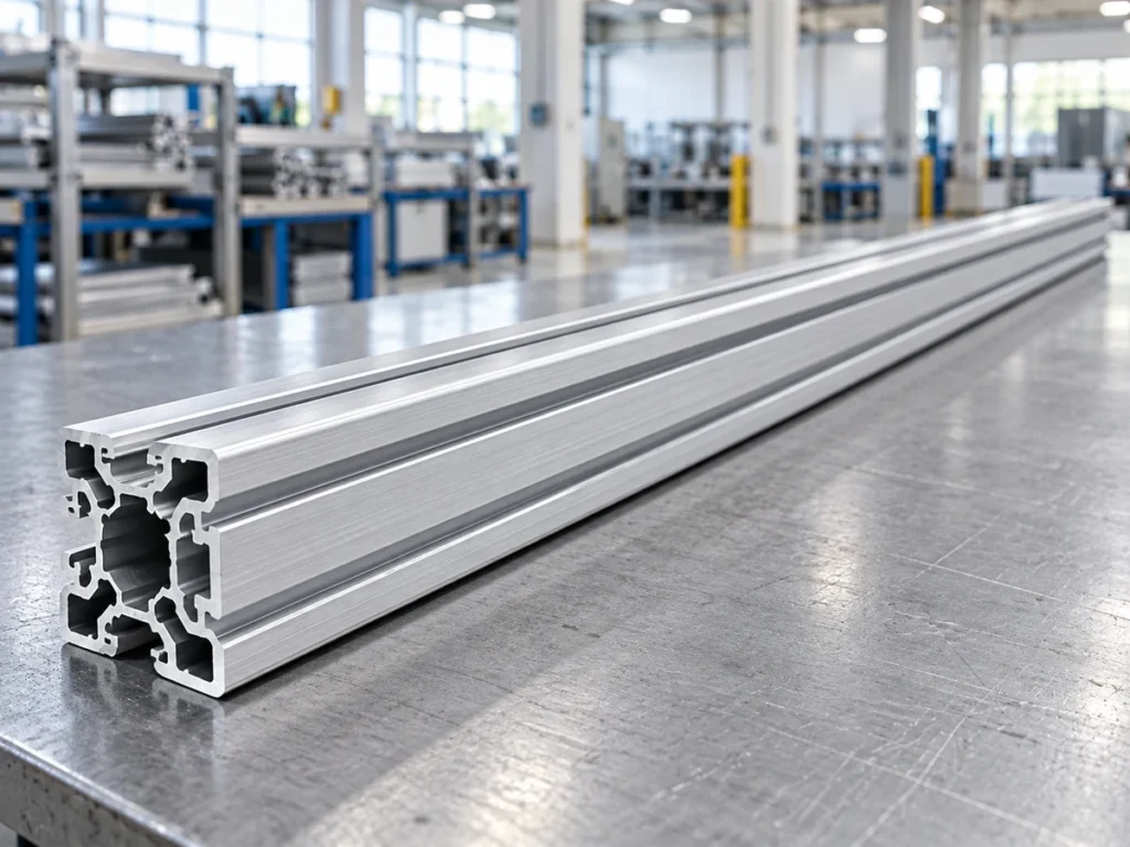
A photograph can help identify the stock being discussed. Use the dimensioned section for the geometry review. An end-view photograph does not supply reliable void area, gap size or the actual die designer’s supporting-base reference.
2. Keep the calculation traceable
Write the selected area, supporting width and calculation method together. Retain the units and the drawing revision from which the values came. Use a consistent unit system so the result can be reviewed independently.
For a fictional geometry, suppose the selected area is 100 mm² and the relevant supporting width is 5 mm. Using the stated area-over-width-squared method gives 100 ÷ (5 × 5) = 4. The units cancel because both numerator and denominator are areas.
| Fictional input | Calculation record |
|---|---|
| Selected area | 100 mm², attached to the identified region. |
| Supporting width | 5 mm, attached to the relevant base reference. |
| Ratio | 100 mm² ÷ 25 mm² = 4. |
This invented example demonstrates arithmetic only. It does not identify a producible profile, classify an actual section or authorize a die. Ask the extruder to confirm the correct geometry and applicable review for the real part.
If one input uses inches and another uses millimeters, convert them consistently before calculating. Keep the original dimensions and conversion record where needed. A dimensionless answer does not repair mixed units in the inputs.
If a gap changes, calculate again from the revised section. Changing the opening may also change the area or another feature. Do not reuse the old numerator automatically while presenting the new ratio as a reviewed design.
3. Preserve the required part function
Explain what the opening must do in the assembled product. It may receive a mating feature, retain an accessory or provide another defined interface. Keep the approved mating geometry and required clearance or engagement in the section review.
A proposed wider opening or shallower recess must be checked against that function. Ask the responsible designer which dimensions can change and which must remain controlled. Record the accepted change on the actual drawing.
Bonnell’s guidance discusses wall balance and symmetry alongside local tongue features. This supports reviewing the whole section with the extruder rather than optimizing one number in isolation. The supplier’s proposal still needs the design owner’s review of the finished part.
Keep applicable load, finish and assembly requirements with that review. This article provides no wall thickness, groove dimension, load rating or clearance that can be adopted as a universal design instruction.
If the opening receives a frame accessory, retain the actual component drawing and fit requirement. The T-slot accessory guide shows why a profile-family label does not complete an interface check.
4. Obtain a supplier-specific review
Send the section, alloy, temper, required dimensions, tolerance references, intended finish and order quantity to the extrusion supplier. Ask it to identify any feature that affects the proposed tool or supply route.
The AEC FAQ gives a general observation that many extruders can readily produce semi-hollows with ratios of three or below, while higher ratios may also be possible with different process demands. Treat that as background. Obtain the actual supplier’s confirmation for the section and required conditions.
Ask for an identified proposed change when a feature needs adjustment. Keep the revised section, affected interface and tolerance consequences visible. Avoid reducing the response to “the ratio is acceptable” if the supplier also changed part geometry.
Keep commercial assumptions attached to the proposal: tooling scope, stock form, quantity, finish route and delivery stage. A design discussion does not establish a quotation, lead time or die life. Confirm those items in the actual supplier offer.
For supplied profile dimensions, retain the agreed inspection reference and relevant stock condition. A successful cut-length check does not establish that a slot or cavity meets its extrusion requirement.
Questions to send the extruder
- Which region and supporting-base dimension does your ratio calculation use?
- Have you reviewed the complete section, alloy and required tolerances?
- Which geometry changes are proposed, and which mating features do they affect?
- What evidence or sample review is needed before releasing the supply requirement?
- What tool, product and delivery assumptions are included in the offer?
Keep the response with the drawing revision and supplier identity. If two suppliers use different assumptions, resolve those assumptions before comparing their offers. A matching ratio value does not establish an identical tool or supplied profile.

Control a proposed section change
Imagine section S22, revision B, contains an opening that the extruder asks to revise. The buyer receives a proposed revision C and a new ratio calculation. This is a fictional handover example.
Keep both drawings identifiable and mark the changed region. Have the design owner review the mating interface, function and relevant inspection requirements. Retain the actual decision before ordering stock under the revised geometry.
Existing stock and already-cut pieces still need their original revision identity. The cut-list revision guide explains how to preserve that distinction. A new section proposal should not silently change the identity of material already received.
Review the resulting stock for cutting
Once the supply section is released, send its drawing, representative stock, cut list and required end condition to the cutting team. Identify the actual contact and support requirements for the supplied shape.
Retain any relevant groove, wall or surface condition that must be protected during handling. Ask JiurunCut to review the cutting requirement through the contact page. Keep extrusion-tool feasibility and section-design approval with the responsible extruder and designer.
Buyer questions
Can tongue ratio be read from a stock photograph?
Use the dimensioned section and the supplier’s identified area and supporting-base reference.
Does a ratio below three guarantee that a profile can be supplied?
Obtain the actual extruder’s review of the full shape, alloy, tolerances and proposed supply route.
Can widening an opening solve the issue without further review?
Review the revised geometry and its mating function with the design owner and extruder.
Does a good saw cut qualify the extrusion die?
The cutting review and extrusion-tool review establish their own required conditions and evidence.