
Two blanks from the same aluminum extrusion meet the length on the cut list, but their end faces appear to lean in the same direction. A blade is an obvious suspect. Replacing it before checking the stock reference, location and mounting may hide the actual cause. An aluminum cut face lean review should first establish what is tilted, relative to which feature, and whether the observation repeats under controlled conditions.
This guide is for a buyer planning a profile-saw trial with a supplier. It separates observations that a sample can support from diagnoses that require the responsible tooling, maintenance or quality team. It supplies no universal squareness tolerance or promise for a Jiurun machine configuration.
Describe aluminum cut face lean before naming its cause
Mark the retained end of each sample, the stock orientation, and the face or feature used as the inspection reference. A cut end can look slanted against an exterior wall even when that wall is twisted or bowed. For hollow or asymmetric sections, identify which walls are actually included in the drawing requirement. The approved part drawing and agreed inspection method decide whether the end passes; a photograph alone cannot.
Keep three observations separate: finished length, end-face orientation and surface appearance. A clean-looking face is not proof of squareness. Equally, saw marks do not by themselves identify a blade that has wandered. Our cut-face squareness drawing guide explains how to specify the face, datum and inspection method. Here the additional question is how to investigate a repeatable lean once those references are settled.
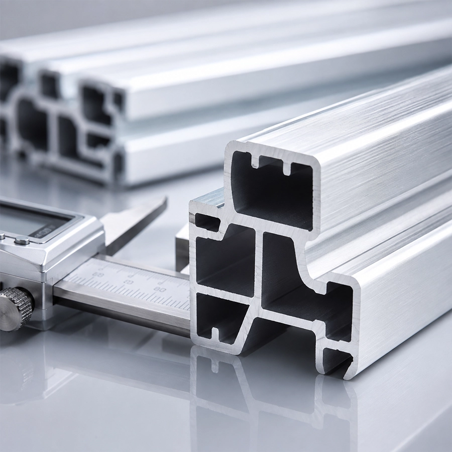
Use a small comparison set with the setup held still
Start with a labeled incoming piece. Record its section, drawing revision, source batch and any visible twist or bow relevant to the selected datum. Then identify the saw configuration actually used: fixture and locators, blade identity, mounting state, feed program and support arrangement. Do not mix pieces from different settings into one apparent trend.
Take an agreed first-off sample and later consecutive samples under the same authorized setup. Label stock orientation and the retained side of each cut. Inspect both ends when the drawing calls for both. Compare end-face readings with the same method and contact locations. A repeated directional pattern is more useful than a single unfavorable part. Document that aluminum cut face lean pattern without treating it as proof of which component caused it.
If the pattern changes when the stock is rotated or when another section is run, the evidence points to a question about stock geometry, reference selection or location. If it changes with an approved remount or another qualified blade, the evidence calls for a tooling or mounting investigation. Each comparison should change one authorized condition at a time, with the responsible technician controlling any machine adjustment. A buyer should request the observations and decision record, not prescribe a shop-floor adjustment from a photograph.
Check location and restraint against the actual section
A locator that bears on a narrow rib, uneven edge or chip can move the effective reference from one piece to the next. A clamp can also push a thin wall away from a locator or deform it while held. Carr Lane’s fixture layout guidance distinguishes locating from clamping and warns against workpiece deformation. That principle supports checking how this particular profile contacts the fixture; it does not certify any one jaw arrangement for a Jiurun saw.
Ask for a view or sketch of the actual contact points, including support near the cut and the position of the stop. Note whether the reference is the same on an incoming piece and a cut sample. Compare the shape while safely held and after release only if the agreed measurement method allows it. A section that springs back after unloading may explain why a measurement made in the clamp conflicts with a downstream fit check. Keep these two states identified in the record.
The square-tube clamp distortion guide treats section-shape change as its own acceptance question. This article is concerned with the orientation of the resulting cut face, so do not use a width reading as a substitute for an end-face result.
Inspect the mounted blade as a system, not a label
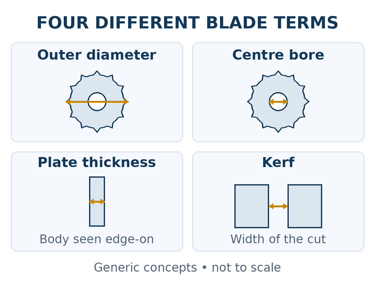
Only after the datum and fixture observations are documented should the blade discussion narrow. Record the actual blade identity and the configuration it was approved for. Plate thickness and kerf are different dimensions; the diagram below helps a purchasing team ask which item was installed, but neither dimension alone proves side deflection. The blade maker’s application guidance, machine instructions and qualified maintenance procedure govern inspection or replacement.
Ask the qualified team to check the documented mounting condition, flanges, blade condition and applicable machine checks before changing a cutting program. A dirty or poorly seated interface is a different question from the blade’s design. The flange remount checklist and blade runout reporting guide cover those narrower topics. Do not infer that either condition exists merely because the cut face leans.
Kanefusa’s nonferrous blade technology notes discuss plate straightness and vibration as blade-design concerns. They describe that manufacturer’s products and principles. They are not a measured cause, remedy or performance specification for the samples in this article.
Turn the comparison into a supplier decision
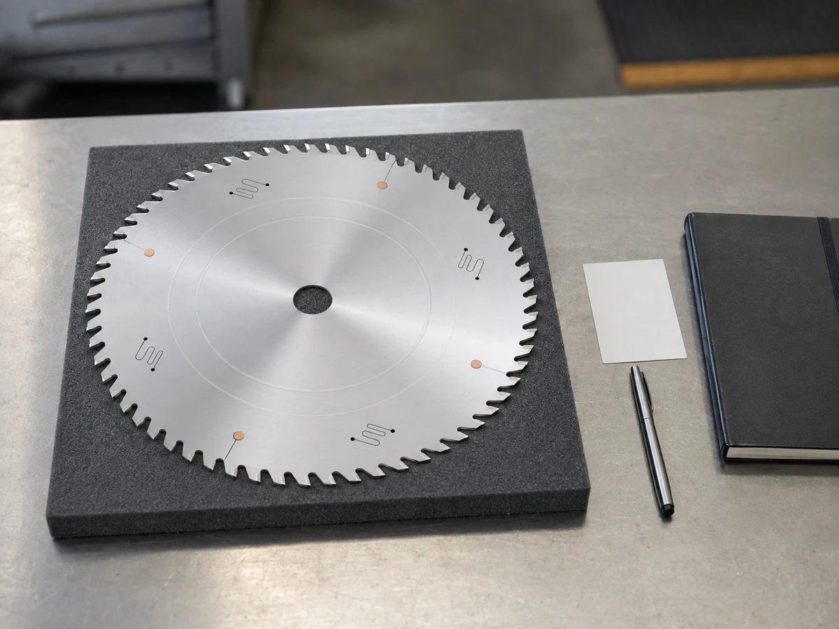
For a purchase trial, request a compact evidence package: the approved drawing and datum, incoming stock identity, machine and blade configuration, fixture contact description, labeled first-off and later samples, inspection method, individual results, and any authorized change between runs. If the samples differ, preserve the unsuccessful pieces and their setup labels. A single selected photograph or the machine display cannot replace the physical sample record.
Use the result to ask the right next question. A stable lean tied to one stock orientation calls for a stock and datum review. A result linked to contact changes calls for fixture investigation. A result that changes only after a qualified blade or mounting comparison belongs with tooling and maintenance. None of these aluminum cut face lean patterns alone establishes the final cause. Have the responsible quality and engineering owners decide what additional test is needed before releasing the process.
The Jiurun Machinery video below shows related profile feeding and sawing motion. It is useful when discussing where a workpiece is supported and cut; it does not show the profiles, blade inspection, end-face measurements or defect diagnosis described here.
Send JiurunCut the section drawing, required end-face relationship, actual stock samples and planned output range when you request a profile-saw discussion. Ask which representative configuration can be trialed and what inspection evidence can be returned. Agree the acceptance method and any model-specific capability claim from the actual proposal and trial, not from this guide.