
Aluminum crevice corrosion deserves attention wherever an assembled joint can keep moisture between adjoining surfaces. For a buyer, the useful starting point is a section view of that joint: where can liquid enter, where can it remain and who controls the finished interface?
This guide organizes four checks for covered seams, corner connections and similar interfaces. Use them to prepare a design and supplier review before ordering cut members. The checklist does not approve a particular joint or prescribe a corrosion test.
What aluminum crevice corrosion means
European Aluminium’s Automotive Manual, Materials section 4.4.11, describes localized attack when moisture enters a crevice between closely adjoining aluminum surfaces. Dirt and salts can intensify the problem. Different oxygen conditions inside and outside the crevice, together with increasing acidity inside it, contribute to the mechanism.
The important purchasing point is that two aluminum surfaces can form the relevant interface. A list showing no steel bracket does not remove the need to review a wet, covered seam.
Keep this question alongside the separate galvanic corrosion review when dissimilar conducting materials also meet. The joint may need more than one mechanism considered; its appearance alone does not establish the cause.
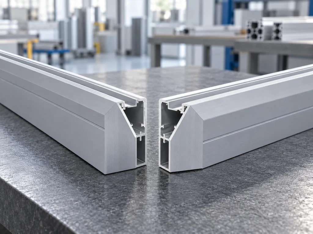
1. Map the interface in its installed position
Ask for a section through the connection, not only a front view. Mark the overlapping surfaces, cover pieces and attached pads. Show which direction faces upward when the customer installs the assembly.
A loose member on a bench leaves this information open. The same piece may become the bottom edge, a vertical upright or part of a covered recess. The purchasing documents should identify the intended position rather than letting each supplier infer it.
European Aluminium’s Design section 3.4.4 discusses joint orientation, drainage and avoiding locations that retain moisture, salts and dirt. It also identifies coating access and the continuing condition of sealants as relevant considerations.
Turn that general guidance into questions for the responsible designer. Which interface needs a drainage review? Which seam must stay sealed? Which surfaces must remain accessible during finishing? Keep the approved answers on the assembly drawing.
Do not alter a specified connection by opening a gap or drilling a drain hole during cutting. Any change belongs in a reviewed drawing revision, with its effect on the complete assembly considered.
2. Describe how the hidden area becomes wet
Write a short exposure description for the interface itself. Identify expected rain, washing, condensation or other known liquid contact. Include foreseeable salt or dirt exposure when the project owner has that information.
Then distinguish entry from retention. A drawing may show where liquid reaches a seam without explaining how the covered area dries or is cleaned. Ask the designer to address that missing part of the review.
Include attached materials in the description. The manual notes that some foam materials can retain moisture and salts next to aluminum. Ask for the specified pad or foam identity and its approved role; “protective foam” is too broad for purchasing.
For a new design, list uncertainties plainly. For an existing assembly, record the actual installed orientation and observations. Do not convert a white deposit, stain or scratch into a confirmed corrosion diagnosis without assessment.
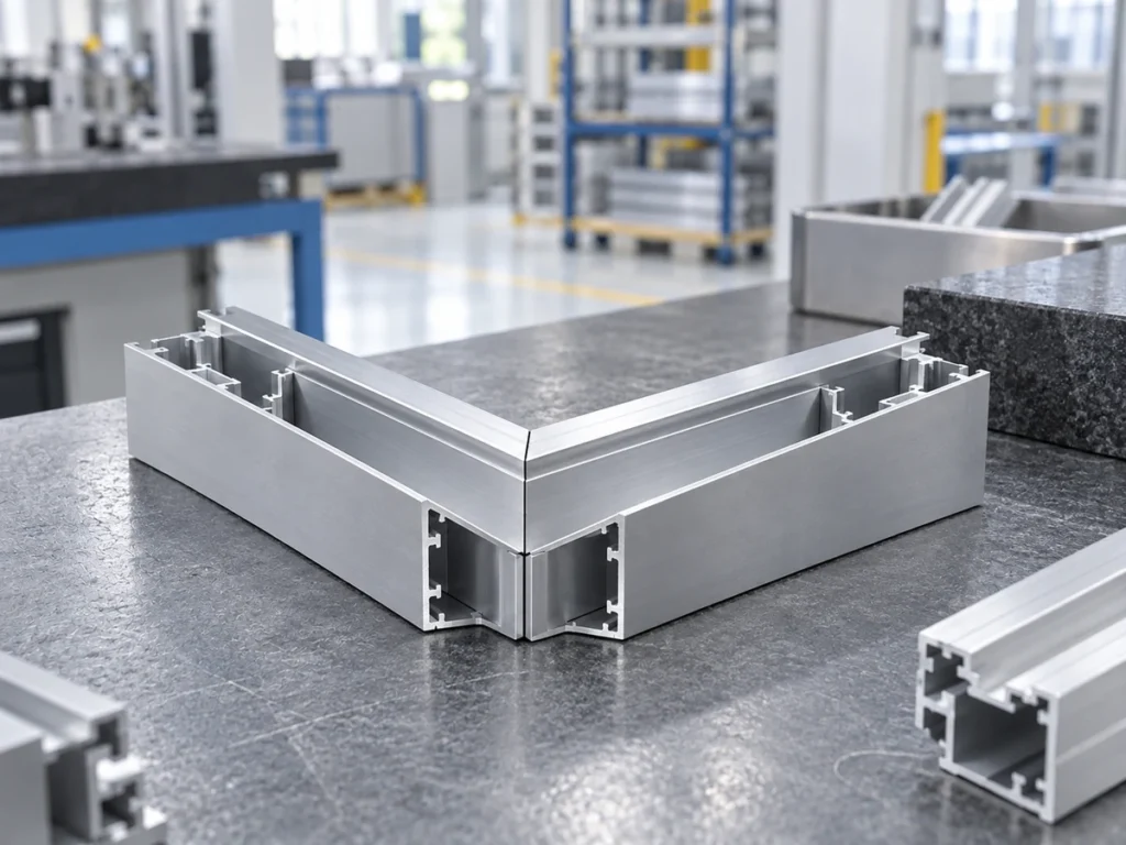
3. Separate drainage, coating access and sealing
These are different design questions. A note saying “protect the joint” does not tell the cutter, finisher and assembler which operation each must perform.
| Review question | Information to put on the drawing |
|---|---|
| Liquid retention | Installed orientation and the approved arrangement for relevant wet areas. |
| Finish access | Surfaces to finish and when they become covered by another component. |
| Sealed interface | Approved material, application scope and assembly responsibility. |
| Later access | Required inspection or maintenance access, if specified by the designer. |
Discuss the proposed finish route before the parts become an assembled frame. Ask the finisher which surfaces the quoted process includes, and ask the assembler which interfaces will be inaccessible afterward.
Keep sealant selection with the party responsible for that design. The material name, application area and assembly instructions should be explicit. A cutting quotation should not quietly include an unapproved sealant substitution.
A tidy visible bead is useful workmanship information, but it does not document the full concealed interface. Ask what records or agreed checks support acceptance of the specified assembly.
4. Review a representative joint before batch release
Choose a sample that represents the intended member shape, mating part and assembly revision. Identify the materials, finish sequence and covered surfaces. If a sample omits a specified pad or cover, record that difference before interpreting its evaluation.
Give the responsible reviewer a clear question. Is the review checking assembly fit, finish coverage, drainage behavior or corrosion performance? These require different evidence; one successful fit check should not become approval of all four.
When an evaluation is commissioned, agree the specimen configuration, method, acceptance criteria and reporting scope with the relevant technical party. Keep the conclusion tied to those conditions. Do not extend an isolated result into an unsupported service-life promise.
Our pitting corrosion guide covers a separate localized-attack review. Refer to it when that mechanism appears in the assessment, while retaining the joint-specific evidence for the covered seam.
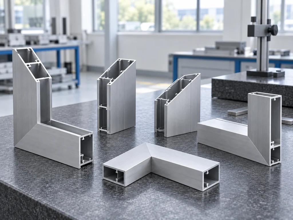
A simple supplier handoff
For cut members, send the drawing revision, stock identity, lengths, quantities and orientation marks needed by assembly. Identify faces that will be covered and any handling requirements for their finish.
Put open decisions in a separate list with an owner. For example: the designer reviews the wet interface; the finisher confirms process coverage; the assembler confirms the approved connection sequence. This keeps unanswered design questions visible before the order moves into production.
Send JiurunCut your profile drawing and cutting requirements for a discussion of the defined cutting work. Include approved interface details so the request describes the members needed by the final assembly.
Questions buyers ask
Can an aluminum-to-aluminum joint need this review?
Yes. The manual describes crevices between adjoining aluminum surfaces. Review the moisture conditions and configuration rather than considering only the metal pairing.
Should I specify one universal gap size?
No general gap value approves every joint. Ask the responsible designer to define the actual geometry, finish access and functional requirements.
Can a clean frame photo establish corrosion resistance?
It shows visible condition at that moment. Approval needs evidence appropriate to the actual assembly and the agreed exposure requirement.