
Aluminum channel cutting starts with the section drawing and a defined finished length. Identify the channel’s outer dimensions, wall geometry, opening and orientation. Then confirm the end condition, locating references and handling requirements with the supplier before treating a machine proposal as suitable for the job.
“U channel” or “C channel” is a useful starting description. It is not a complete section specification. This guide explains how to turn that description into a clear cutting brief.
Keep these three items separate
- The channel section: outside dimensions, wall geometry and opening.
- The finished part: length, end angles, tolerances and edge condition.
- The proposed process: approved orientation, support, clamping and handling.
On this page
Name the section in your aluminum channel cutting brief
Use a section drawing, stock code or die number that identifies the actual profile. Include the material specification, temper and finish from the approved purchase documents. Keep the revision visible alongside the profile identity.
Record the overall width and height, the base or web thickness and the leg geometry. If the legs have different thicknesses, tapered faces, returns or other features, show them explicitly. One nominal thickness may not describe the entire section.
Hydro’s City of Industry standard-shape catalog separates several channel families, including tapered-leg and sharp-corner sections. This classification illustrates why the section family matters. The catalog bears a Version 2024 label; it is a shape reference, not proof of current stock availability or JiurunCut cutting capacity.
Similarly, Cut2Size Metals describes two channel forms with different leg geometry. Its descriptions concern the products it supplies. For your cutting brief, retain the actual drawing rather than assigning a geometry solely from an alloy name or the letter U or C.
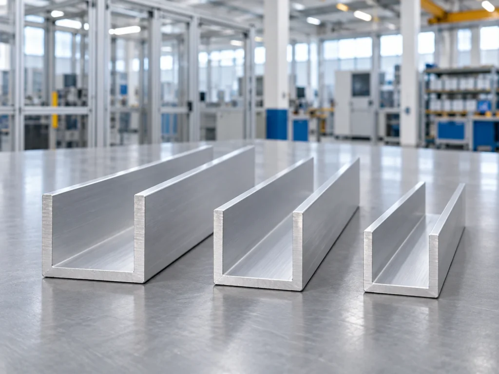
Distinguish the outer width from the inner opening
A channel may need to fit over another component or locate a panel between its legs. In that case the opening can matter as much as the outside envelope. Name which dimension is required instead of writing only “channel width.”
For a fictional ideal section with parallel legs and no corner radii, let the overall width be 50 mm and each leg thickness be 3 mm. The inner width between the parallel faces is 50 − 3 − 3 = 44 mm. The subtraction describes that simplified section; it is not a fit recommendation.
The actual opening near the base may be affected by corner geometry. Tapered legs also mean that the spacing can vary with height. Identify the location at which the opening is specified or inspected, using the drawing rather than an assumed subtraction.
If mating clearance is important, let the responsible designer specify it and its limits. Cutting the channel to length does not automatically correct the incoming section width or opening. Ask whether those incoming dimensions need a separate review.
A quick sketch with outside width, leg height and the required opening makes the request easier to read. Keep units consistent; our inch-to-millimeter cutting guide explains how to preserve the drawing’s dimensional intent during conversion.
Define the length of the delivered channel part
State whether the requested length belongs to a saw-cut part, a machining blank or a completed component after further processing. These are different delivery scopes. A short phrase beside the length can prevent the quote from answering the wrong question.
For square ends, identify the agreed longitudinal measurement reference and any end-condition requirements. For angled ends, show the controlling edge or point, the cut direction and the view. A single length without a reference can be ambiguous.
Consider a fictional order for 40 finished channels, each 300 mm long. Their combined finished length is 12,000 mm. That total does not establish how many stock bars must be purchased because kerf, trims, usable stock length and the proposed process remain separate inputs.
If the 300 mm dimension is instead the completed length after machining, the required saw-cut blank may differ. Keep the approved machining allowance in the cutting brief. Do not ask the operator or supplier to invent it from the finished dimension.
Use miter-length references for angled parts and blade cutting-width information when reviewing the stock plan. Neither changes the drawing’s finished-length requirement.
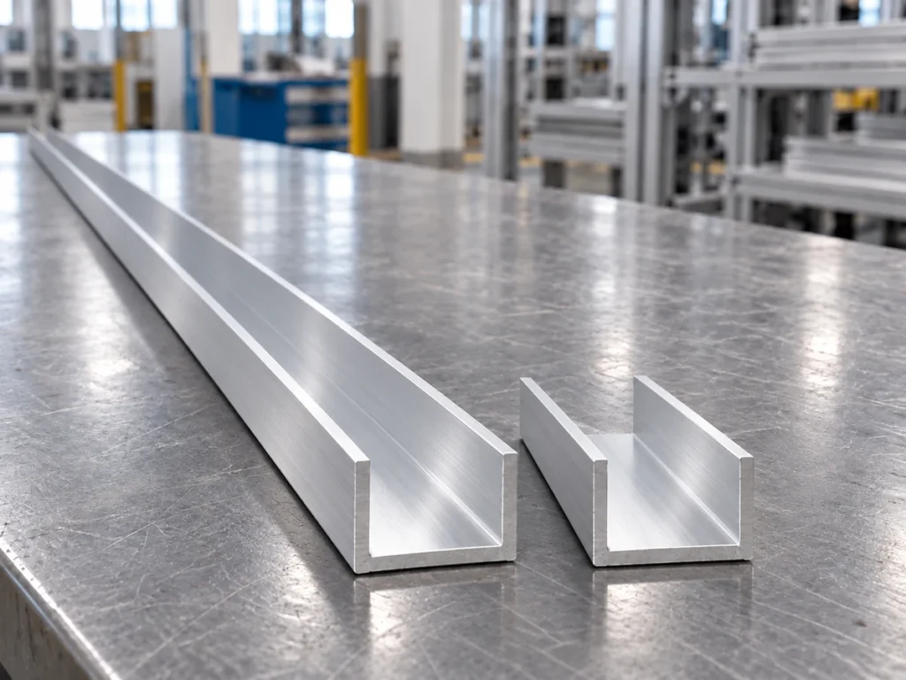
Review orientation, supports and permitted contact
Show the orientation proposed for the channel during the supplier’s review. An open side facing upward is different from a rotated section. Use an identified drawing view so words such as top, left or front have a shared meaning.
Mark the surfaces that may be contacted and any surfaces with a visible finish or functional requirement. Ask the supplier to identify the approved locating and restraint arrangement for that section. Do not infer an operating setup from the illustrative photos.
The open section needs its actual geometry considered in the machine proposal. Supports, contact pads and clearances should be assessed together with feeding, cutting and removal. A profile fitting within an external size envelope does not establish that the whole process is suitable.
Keep the clamping equipment scope in the proposal. Identify any job-specific tooling, the profile families it covers and the relevant revision. A change to the section or finish should be visible to the team responsible for approving that arrangement.
These are procurement questions for the supplier. The approved machine instructions govern operation; this article does not prescribe clamp pressure, blade feed, contact force or a channel-loading sequence.
Describe the ends that the next process needs
Write the required end angles and tolerances, together with the length reference. Where the drawing calls for a particular end-face relationship, state the feature and the agreed inspection method. “Straight cut” alone may leave the acceptance condition unclear.
Specify whether the part is delivered as cut or with an approved edge treatment. A request to remove a loose burr differs from a dimensioned chamfer. Avoid allowing an unspecified edge treatment to alter a functional corner, assembly reference or visible finish.
Record the intended downstream process. A channel that will be machined, coated or assembled may need different delivery information. Let the relevant drawing and process owner define those requirements instead of adding generic promises about assembly fit.
Ask for representative samples that cover the meaningful differences in the job, including relevant sizes, end angles and surface conditions. Identify the sample and drawing revision in the review record. A photograph is context; actual acceptance rests on the agreed observations and requirements.

Prepare a one-page channel brief
Organize the information in the order the supplier needs to read it. The section identifies the material being handled. The finished-part drawing identifies what must be delivered. The quantity and job range identify which differences the proposal needs to cover.
- Section identity: stock code or die number, drawing revision, material specification and finish.
- Section geometry: outer dimensions, leg and web details, corner geometry and any required opening.
- Part requirement: finished length reference, end angles, tolerances and edge condition.
- Job range: stock lengths, finished lengths, quantities and different channel families.
- Review scope: proposed orientation, permitted contacts, tooling and agreed sample evidence.
If one item is not yet known, label it as open and identify who will confirm it. An explicit open point is easier to resolve than an assumption hidden in a quote.
Keep the final accepted brief with the machine proposal. It helps the purchasing team see which channel jobs were reviewed and which require further confirmation. It also gives future revisions a clear starting point.
Questions about aluminum channel cutting
Does U channel always mean parallel legs?
Do not rely on the name alone. Suppliers use shape names alongside more specific section families and drawings. Confirm the actual geometry, including leg taper and corner details.
Is outside width enough to specify a channel that fits over a part?
No. The required opening, its measurement location and the mating requirement need to be defined by the responsible drawing. Corner geometry and tapered faces can matter.
Can the same saw proposal cover several channel sizes?
It may, but the supplier needs to confirm the actual section families, orientations, part lengths, angles and tooling scope. A shared name does not establish shared process approval.
What should I send for a channel-cutting proposal?
Send the section and part drawings, material and finish specification, quantity, stock length range and finished requirements. Identify open points and provide representative samples when requested.
Review your channel cutting requirements
Send JiurunCut the channel drawings and job brief to discuss a suitable machine proposal. Include the required opening and finished-length reference so the review addresses the part you actually need.