
Aluminum blind tapped holes need separate definitions for the required thread and the space available beneath it. State the complete thread designation, required usable threaded length, hole-depth requirement and finished condition. Confirm the mating fastener and an inspection method that checks the actual requirement.
A blind hole does not pass through the part. Its internal geometry can be difficult to judge from an external photograph or a simple CAD view. These five drawing checks help buyers obtain a clear machining quotation and a useful first-piece review.
Keep three questions separate
- What thread must the part contain?
- How much usable thread does the design require?
- What hole geometry and inspection method will support that requirement?
On this page
1. Identify aluminum blind tapped holes completely
Start with the thread system and designation on the approved drawing. A nominal diameter alone does not tell a supplier everything needed to identify a thread. Make the pitch, applicable class and handedness clear wherever the design requires them.
Give every hole group a stable reference. Two features that look similar may have different requirements. If a drawing contains several blind threaded holes, connect each callout to the correct view and state which repeated features it covers.
Autodesk’s holes and threads overview treats hole geometry and thread characteristics as distinct settings. Thread length, offset and designation belong to the thread definition; hole placement and geometry also need to be specified.
Do not infer the final callout from the visible diameter in a model. Send a controlled drawing with the model and ask the supplier to flag any inconsistency before quotation or machining. Identify which document controls the requirement.
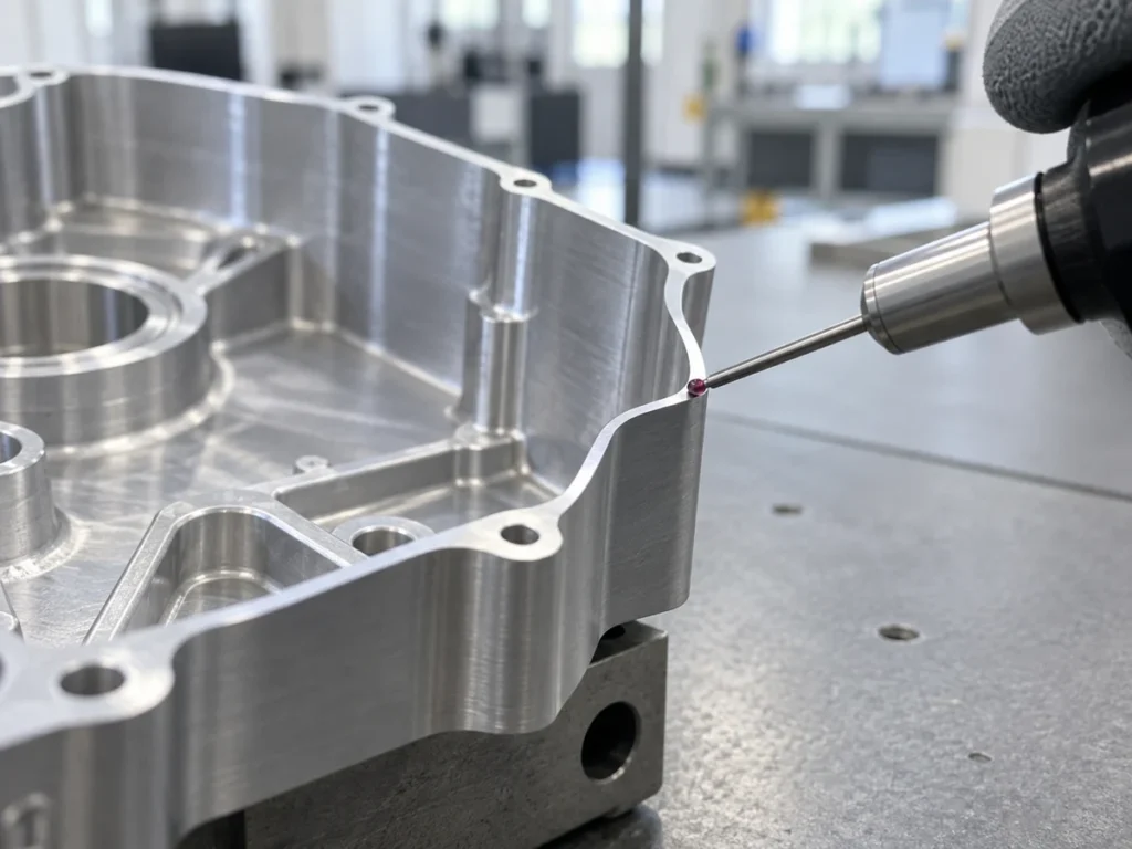
2. Define the required usable threaded length
Explain what the length requirement refers to and where it starts. If the design requires a minimum length of complete usable thread, say so in the approved callout. Keep that requirement separate from an overall hole depth.
A dimension that merely says “deep” invites interpretation. Does it describe the drilled feature, a threaded region or an assembly requirement? Ask the designer to resolve the wording rather than allowing the purchaser and machinist to assign different meanings.
Identify any thread offset or unthreaded region at the entrance. Autodesk’s thread creation guide describes controlling thread length and offset separately, as well as distinguishing modeled and cosmetic threads. A CAD representation is useful context, but the order still needs a clear final requirement.
Leave process choices with the machining supplier unless the design specifies them. The buyer should communicate the required finished geometry and ask the supplier to confirm feasibility. Copying a tooling depth from a different job does not establish the usable length for this part.
Do not select engagement from diameter alone
The required engagement belongs to the joint design. Ask the responsible engineer to consider the actual materials, fastener, loading and surrounding part geometry. Do not approve a joint by applying one universal multiple of the nominal thread diameter.
A supplier may propose a revised length or a different fastening arrangement. Record that as a proposal awaiting approval. It should not replace the released drawing merely because the change is convenient to manufacture.
3. Clarify the hole envelope and remaining material
Show a section or detail view when the bottom of the hole matters. Identify the surface from which depth is measured and distinguish the cylindrical region from any drill-point geometry. Make the governing definition explicit in the drawing.
A model with an angled bottom and a drawing with a single depth number can still leave a question about the measurement endpoint. Ask whether the callout applies to the stated cylindrical depth or the deepest point. Do not resolve that question by guessing from a shaded image.
Identify nearby features and any design restriction on breakout. A hole close to an internal cavity, pocket or opposite face needs a clear drawing relationship. The design team should define any required remaining material rather than leaving it to a general shop preference.
Sandvik Coromant’s tap-selection overview considers workpiece material, blind or through-hole geometry, batch requirements and threading depth. This supports a process review for the actual feature instead of treating every tapped hole as the same operation.
Ask the supplier to confirm that its proposed process can achieve the required thread within the permitted hole envelope. This is a feasibility question, not a request for the buyer to prescribe a tap, drill setting or machining cycle.
4. Review the mating fastener and joint stack
Name the mating fastener or provide its controlled specification. Include the parts between its bearing surface and the threaded component, such as an approved bracket or washer. Review the assembled relationship rather than the loose screw alone.
Ask the designer to distinguish required thread engagement from any clearance needed at the bottom. A screw reaching the bottom is not the same condition as a joint achieving its intended clamp. Confirm the approved assembly requirement and inspection approach.
If the mating component changes thickness or the screw changes length, revisit the joint. A thread callout can remain unchanged while the assembled relationship changes. Keep these revisions connected rather than checking each purchase item in isolation.
Do not use a production screw as an unspecified universal gauge. If a functional fit check is appropriate, identify the component, method and acceptance criterion. Keep it separate from any dimensional or thread-gauging requirement on the drawing.
5. Specify the finished inspection
State the stage at which the requirement applies. A hole checked before a surface treatment may need a different review from the finished part delivered for assembly. Make the finishing sequence and any protected areas clear to the responsible suppliers.
For powder-coated parts, connect the thread identity to the approved masking map. If an insert is required, use its approved definition and review the thread-insert order requirements rather than describing the finished hole as a directly tapped thread.
Agree the inspection record before first-piece review. It should identify the part revision, hole group, thread requirement, relevant depth definition and agreed results. Ask the responsible inspection team to select suitable equipment and a method capable of checking those requirements.

Record a result for the feature being checked
Keep a general “thread accepted” statement from hiding a missing depth check. Where separate acceptance criteria exist, record them separately. If a check cannot establish the required condition, resolve that limitation before approving the part.
The first-article inspection guide helps organize drawing-linked evidence. Preserve any open issue as an open issue; do not turn an incomplete review into an unconditional acceptance.
A practical review note
Fictional example: a housing drawing identifies a blind threaded hole as H2. The review team finds that “depth” could refer to either the drilled feature or the usable thread. It asks the designer to separate the requirements and provide a section view showing the intended reference surface.
The machining supplier then confirms feasibility against that revised definition. The first-piece record checks the agreed thread and depth requirements separately. This example describes a communication workflow, not a measured result or completed customer project.
Connect the hole to blank preparation
For an extrusion end feature, identify the prepared end and the drawing reference used to locate the hole. Our extrusion end-tapping guide covers that upstream handoff. This article focuses on the internal blind-hole definition.
For a JiurunCut cutting inquiry, send the profile drawing and finished-length requirements. Include downstream drilling or threading requirements that affect blank preparation. Obtain machining and joint-design approval from the parties responsible for those operations.
Buyer questions
Are thread depth and drilled depth interchangeable?
No. Clarify each requirement and its reference before releasing the drawing. A single depth number should not carry two different meanings.
Does a visible CAD thread prove the finished part conforms?
No. The model represents design intent. Acceptance requires the approved specification and appropriate inspection evidence for the manufactured part.
Can every aluminum joint use the same engagement rule?
Have the responsible designer establish the requirement for the actual joint. Material, loading and part geometry need consideration.
What should accompany a blind-thread quotation request?
Send the current drawing and model, complete thread callout, separate depth definitions, relevant mating-part details and finishing requirements.