
An air-handling-unit (AHU) frame can be cut to the correct nominal length and still arrive with the wrong face prepared for the seal. The useful question before releasing aluminum members to a saw is simple: where does the AHU frame gasket actually run, and what happens when that path meets a cut end or corner? A saw supplier can control a defined metal blank. The casing designer or assembler must define the approved profile, connector, gasket and sealing sequence that makes those blanks useful.
Start with a cross-section and one approved corner sample, then trace the gasket route with a finger from panel edge to frame member to joint. Mark which surfaces must remain accessible after cutting. This exercise prevents a cut list from silently treating every extrusion face as interchangeable.

There is no universal AHU frame gasket route
Two published system descriptions show why a generic “cut the AHU profile” instruction is incomplete. Enginia describes a simple-wing aluminum frame joined with plastic corners and omega joints, where a closed-cell foam adhesive gasket is normally applied to the fin. In a different design, Daikin’s D-AHU Professional brochure describes a gasket inserted into a dovetail slot in double-chamber aluminum profiles, with three-way glass-reinforced nylon corners. These are examples of particular systems, not interchangeable instructions for an unspecified AHU.
An adhesive AHU frame gasket on a fin and a separate gasket insert retained in a slot create different questions for cutting and downstream assembly. Which side of the extrusion faces the panel? Does the seal arrive separately, before the cut, or after it? Does the approved corner piece continue the gasket path, compress it, or require another sealing operation? The released system drawing and supplier instructions must answer those questions; the saw operator should not improvise them from a photograph.
Walk the path before assigning a saw datum
Lay the actual section next to its drawing. Identify the panel-facing fin or seal-retaining groove and mark it on the sample. Follow that mark through each upright, rail and corner. Only then specify the clamping face, stop reference, cut orientation and left/right hand of each blank. A symmetric-looking outer shape may hide a functional internal side; rotating the stock to make feeding easier can reverse the intended panel interface.
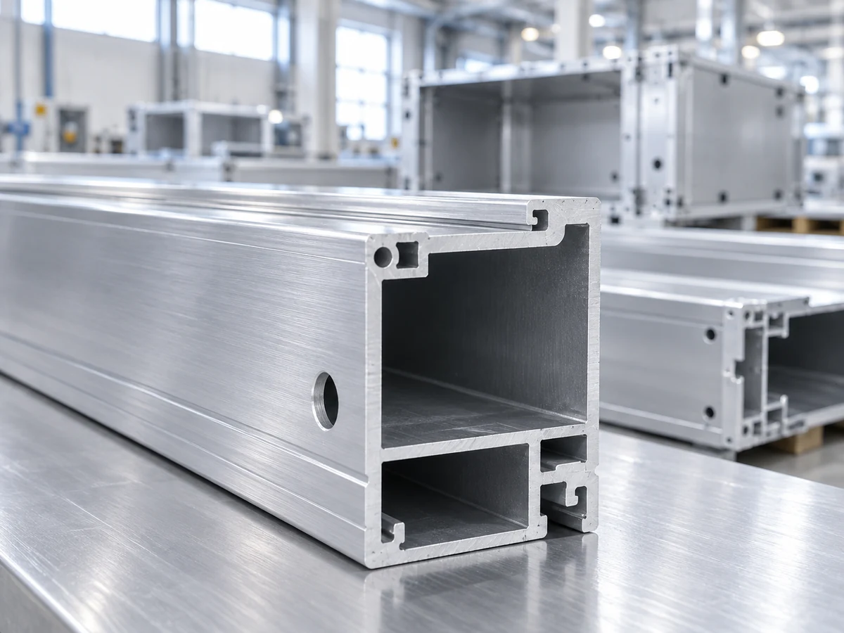
The cut drawing should name a datum that a technician can actually find on the stock. It should also state whether the length is measured over the metal only, between corner shoulders, or over an assembled frame. Those values can differ even when a purchase order uses the same phrase “finished length.” Where the section is handed or has a designated sealing face, label the blank rather than relying on a pile of visually similar parts.
Make the corner a separate acceptance point
A clean, square metal end is useful, but it cannot by itself establish gasket continuity. The approved corner may occupy an internal chamber while the seal runs along a different fin or slot. Dry-fit a first-off set with the specified corner and panel or representative gauge. Check that the joint seats without forcing the member, that the intended seal path is reachable, and that the cut end does not foul the connector. Record any burr or deformation at the edge that contacts the seal or connector.

Do not transfer a corner detail from one manufacturer’s frame to another. Even within an AHU, fixed panels, removable panels and doors may use different interfaces. Systemair’s KA description, for example, discusses aluminum sections with nylon corners and sealing arrangements for panel and door interfaces. Its details help illustrate the need to identify the specific interface; they do not certify a different frame or a JiurunCut saw setting.
Separate the metal trial from the casing test
A practical first-off saw trial can document the released stock ID, orientation, cut length against the stated datum, end squareness, visible edge condition and fit with the approved corner sample. Use the project drawing’s tolerances and inspection method rather than a generic number borrowed from another profile. If a gasket is already fitted when stock is cut, the process owner must also define how the seal is restrained, protected and finished at the end. If the gasket is installed later, the saw acceptance record should not imply that insertion or sealing is complete.
The following JiurunCut channel video shows a straight aluminum-profile feeding and cutting operation. It is equipment context only: it does not show this AHU profile, a gasket, an approved corner assembly, a customer trial or an air-leakage result.
Air leakage, panel compression and durability belong to the assembled casing and its applicable test procedure. A visually good saw blank does not establish those outcomes. Keep the boundary explicit in both the supplier quotation and the inspection report: metal cutting can be accepted against a drawing, while gasket installation and casing performance require their own responsible parties and evidence.
Release a small, unambiguous handoff
- System identity: approved profile and corner part references, revision and physical section sample.
- Seal route: marked gasket-bearing face, panel or door interface, and the approved joint detail.
- Cut definition: each member’s metal length datum, orientation, handedness, end condition and drawing tolerance.
- Work boundary: whether stock arrives with a gasket, whether the saw supplier performs any seal work, and who assembles and tests the casing.
- First-off review: representative cut pieces and approved corner sample checked together before a production batch is released.
If your team is still separating frame members from connectors and other kit items, see our AHU frame kit bill-of-materials guide. Once the system and AHU frame gasket path are fixed, send JiurunCut the released aluminum section drawing, representative stock and cut-member requirements for a focused saw discussion. The casing designer remains the authority for seal design and performance acceptance.