
Miter, bevel and compound cuts need different cutting directions relative to the way an aluminum profile is held. For repeated miter work, review a fully automatic multi-angle aluminum cutting machine. If the end face also slopes through the profile height, ask the supplier to confirm the required bevel or compound setup. Start with the finished end shape and marked reference faces, then check which movements the proposed machine can provide.
Three things to remember
- Define the profile’s bottom and side reference faces before naming the cut.
- A compound end combines two angle directions in the same cutting position.
- Confirm the actual cutting movements and fixture for your drawing.
On this page
Miter, bevel and compound cuts: a quick comparison
These terms use a defined workpiece position. Imagine the profile’s bottom face resting on a support and its side face locating against a fence. Keep that position unchanged for this comparison.
| Cut type | Common saw movement | Finished end to show |
|---|---|---|
| Square crosscut | No miter rotation or bevel tilt | An end square to the profile’s length |
| Miter cut | Horizontal angle change with the blade upright | An end angled across the width and square through the height |
| Bevel cut | Blade tilt with no horizontal miter angle | An end sloping through the height |
| Compound cut | Miter rotation and bevel tilt together | An end angled in both directions |
The Bosch 5412L manual, pages 24–26, distinguishes these common saw terms. Its machine settings and specifications do not apply to Jiurun equipment.
A compound cut can leave one flat end face. The word describes the combined miter and bevel angles, as explained in DEWALT’s compound-miter explanation.
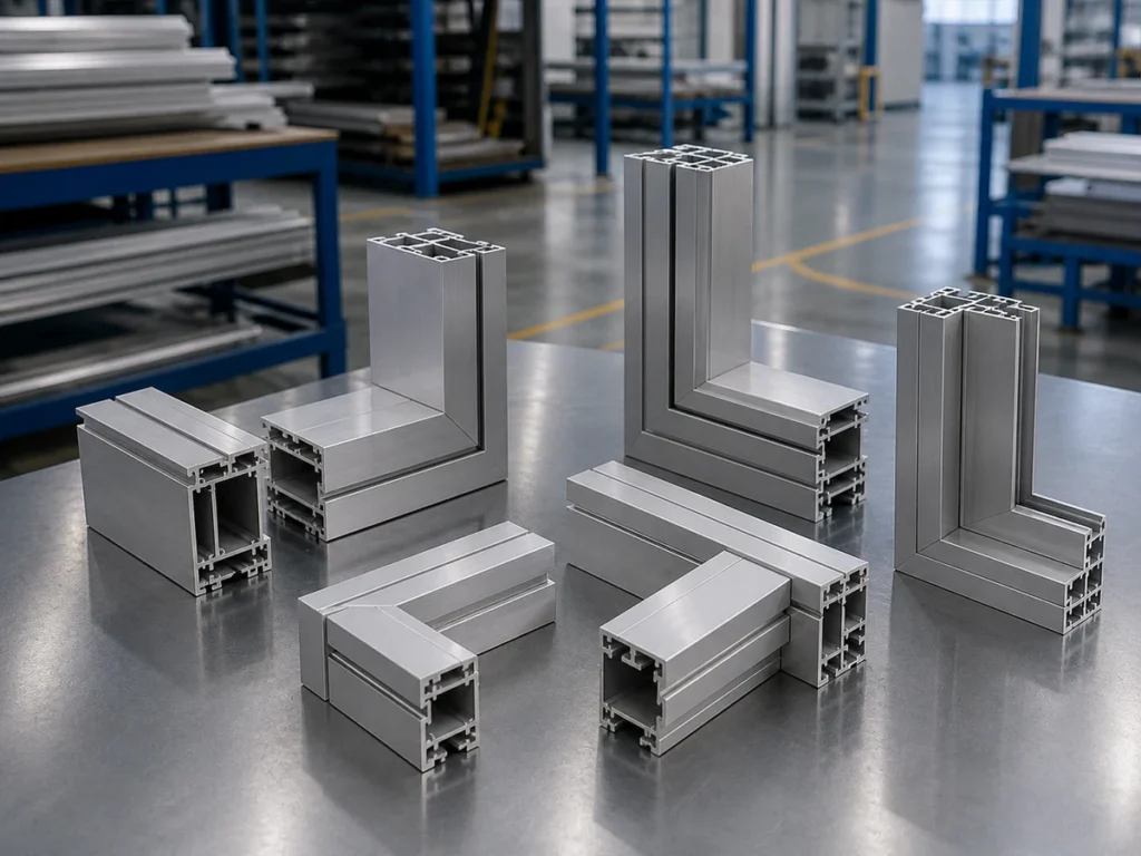
Which cut does your part need?
Send a clear part photo or sketch and point out the end that must meet the next component. You can start with what you have.
Mark the profile faces before naming the cut
Label the intended bottom reference as face A and the side reference as face B. For an open or irregular extrusion, mark the actual locating surfaces. Add an arrow along the stock and identify the end being cut and the piece you will keep.
Turning the profile changes its relationship to the blade. A different orientation may change which saw movement produces the required face. Any alternative position needs a supplier-approved support, clamping and feeding arrangement for the real section.
Ask the supplier to show the proposed position alongside your drawing. Check that the visible face, internal channels and mating features remain on the correct side. For angle references and length definitions, use our aluminum miter-cutting guide.
Show the required drawing views
A single view can hide part of the end shape. Send the views that make both directions clear:
- Top view: shows the end angle across the profile width.
- Side view: shows whether the end slopes from top to bottom.
- End or cross-section view: identifies the profile shape and reference faces.
- Assembly view: shows the mating component and how the faces must meet.
Mark the required angles on their reference faces, including the direction of each slope. Identify left- and right-handed parts separately. A clear three-dimensional view can help, but the supplier still needs enough dimensions and references to confirm the cutting position.
If one view is missing, flag it as pending. Ask what else is needed to establish the finished face before the machine configuration is agreed.
Two aluminum frames, different cutting requirements
Illustrative example: a flat guard frame. Rectangular aluminum tubes form a frame that lies in one plane. Each corner end is diagonal across the tube width and square through its height, with the same bottom reference maintained. This is a miter-cutting requirement in that position. Repeated lengths and end angles are a reason to review an automatic multi-angle setup.
Illustrative example: a sloping enclosure member. A tube joins an upright member. The drawing requires its end to angle across the width and slope through the height while the marked bottom face remains down. This is a compound-end requirement in that position. The supplier must confirm how the proposed configuration creates both directions.
Both parts may look like ordinary frame members in an assembly photo. Their end views reveal the difference. Keep those views with the proposed machine and fixture review.
What must an automatic multi-angle saw confirm?
The JR-550CNC-CORNER fully automatic multi-angle aluminum cutting machine is a Jiurun option to review for recurring angled parts. Bevel and compound requirements need configuration confirmation from your drawing.
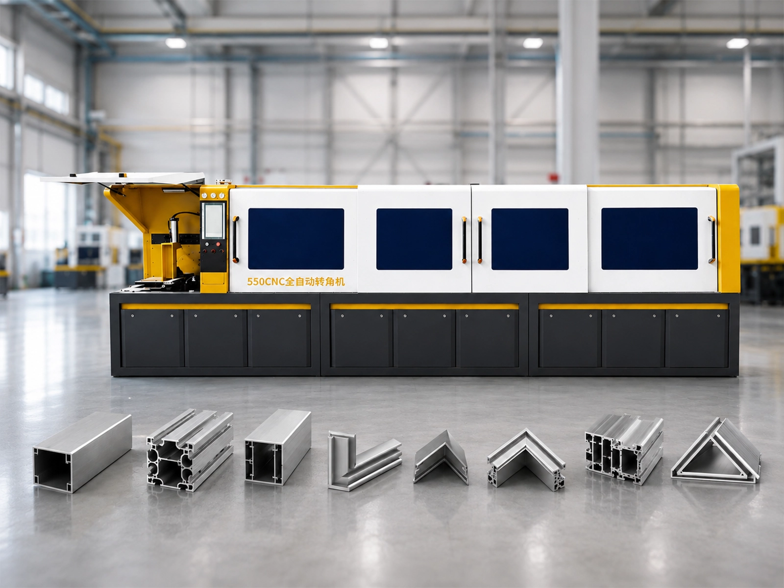
Ask the supplier to explain these points for the exact equipment being quoted:
- Cutting directions: Which movement changes the miter angle? Which movement or approved profile position creates a bevel?
- Combined position: Can the required angle and tilt be used together with this profile and fixture?
- Opposite ends: How will the setup produce each handed version and each end direction?
- Operator steps: Does the job require profile turning, a fixture change or a manual adjustment between parts?
Have the answer identify the actual movements. An axis count or a list of programmable angles does not describe them. Include any required reorientation in the production review.
For the wider decision about repeated jobs and the automatic cycle, see how to choose an automatic multi-angle aluminum cutting machine.
Watch an automatic angle-saw demonstration
Jiurun’s own channel provides this angle-saw demonstration. Use it to discuss the profile position and cutting cycle. It does not establish a bevel or compound configuration for your part.
Does your end angle in both directions?
Share the top and side views, with the profile’s bottom face marked. Ask JiurunCut to review the cutting movements and any repositioning required.
Confirm the finished end face
If sample cutting is agreed, use a part that includes the required end directions. Check the finished face against the drawing in both relevant views. A single angle measurement on one visible face may leave the other direction unverified.
Record the marked reference faces and cutting position with the sample. Check how it meets the real mating part, including internal features that locate the connection. Agree which measurements and fit checks will establish acceptance.
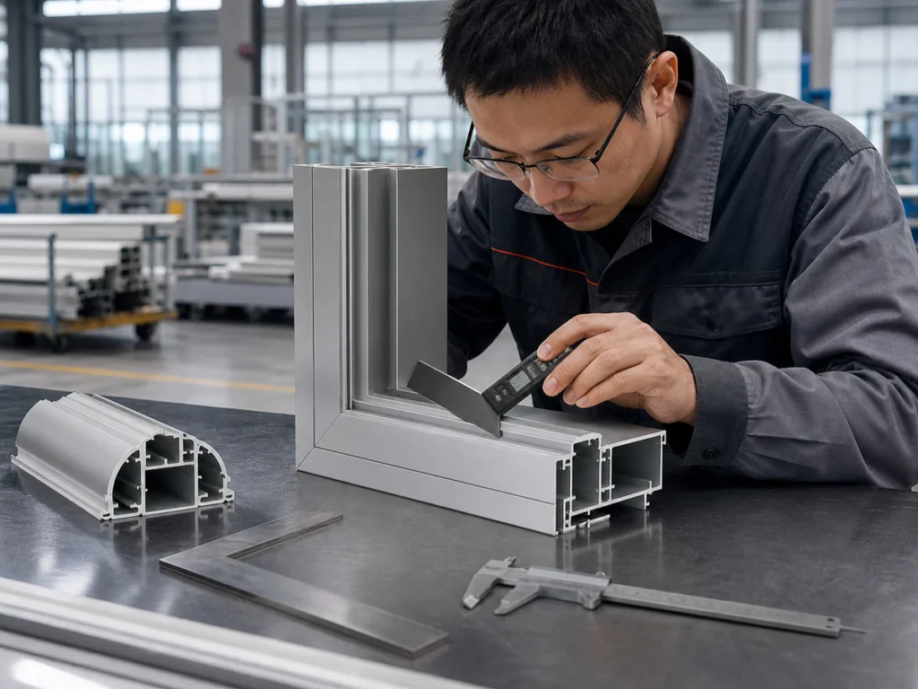
Once the cutting position is clear, confirm that the profile can be supported and held throughout that cut. Our cutting-capacity diagram guide covers the separate usable-capacity review.
Start with the part you have
You can begin with a drawing, a clear profile photo or a picture of the assembled corner. Point out the end shape and tell us what is uncertain. Mark the intended bottom face if you can.
Required quantities and repeated end combinations help explain whether an automatic multi-angle machine suits the production job. Missing dimensions or views can be clarified as the review develops.
Discuss your end-cutting job with JiurunCut
Send the details you have and ask which configuration can produce the required faces. We can discuss the drawing review, sample-cutting scope and equipment to include in a quotation.
Miter, bevel and compound cuts: buyer questions
Does multi-angle cutting mean compound cutting?
Confirm the cutting movements. Several programmed end angles in a batch do not establish that the machine can combine miter rotation and bevel tilt for the same end in your required position.
Does a three-axis machine name prove the required cutting directions?
No. Ask what each controlled axis moves and how the proposed setup creates the faces on your drawing. Keep the exact model, layout and fixture with that answer.
What if my end detail also includes a chamfer, slot or step?
Mark each feature separately. Ask which operation will produce it and whether another process is required. Confirm the complete end detail rather than assuming an angled saw cut supplies every feature.
Sources and scope
The linked Bosch and DEWALT manufacturer manuals support the generic cutting terminology. Machine identity comes from Jiurun’s machinery brochure, physical PDF page 13, and the JR-550CNC-CORNER product page. The drawing-review questions and frame examples are practical buying guidance. Confirm the current configuration, cutting directions, profile position and acceptance requirements with the supplier.