
An aluminum rectangular tube order needs a section view and a clear reference for each relevant face and end. A cut length identifies the piece along its axis. It does not identify which face later receives a hole or points outward in an assembly.
Use the released drawing to connect the stock section, cut blank and finished member. The fictional example below shows how three references keep those stages readable. Its dimensions are teaching assumptions, not stock availability, load ratings or an approved machine setup.
1. Label the aluminum rectangular tube faces in one view
Consider an original fictional hollow section with an outside envelope of 50 mm across and 30 mm high. Look at its marked end E in the direction shown on the drawing. For this example, label the outer faces clockwise: F1 at the top, F2 on the right, F3 at the bottom and F4 on the left.
These are local explanatory labels, not standardized datum symbols. The actual drawing must define its references using the applicable drawing rules. Keep the viewing direction beside the labels so another person can interpret them consistently.
| Face in the example view | Nominal outside span |
|---|---|
| F1 top and F3 bottom | 50 mm across the outer envelope |
| F2 right and F4 left | 30 mm along the outer envelope |
The nominal spans describe the example’s outside envelope. They do not establish usable flat seating width, corner geometry or the internal opening. Those features need the actual controlled section definition.
SAF’s rectangular-tubing listing illustrates a supplier description with separate section-number, A, B, T and stock-length fields. It labels that listed range as sharp-corner extruded tubing. Read the drawing associated with the actual offered section rather than copying a broad shape name.
For your aluminum rectangular tube, retain its complete profile designation and corner details. A listing’s A and B labels belong to its accompanying section reference. Do not assume that every supplier uses those letters for the same faces in your assembly.
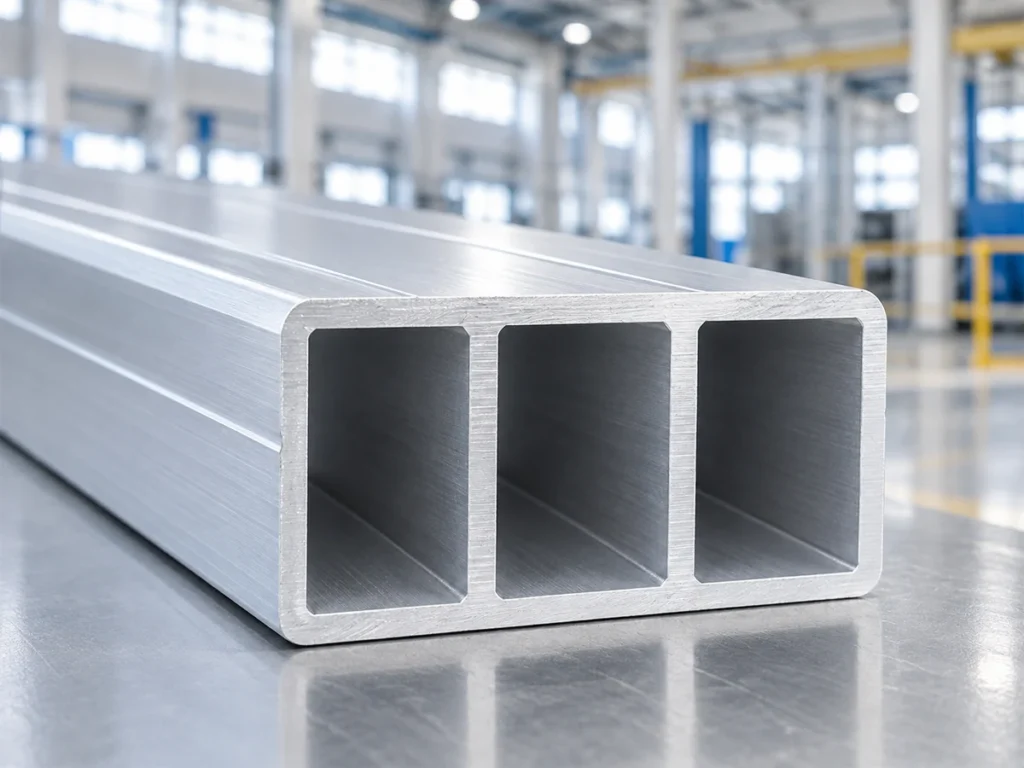
What changes when the piece is rotated?
If the fictional section is turned through a quarter turn about its length axis, its outside envelope becomes 30 mm across and 50 mm high in the new view. The material has not changed, but its position in the assembly has.
Keep the physical face identities connected to the approved orientation. Do not rename a different face F1 merely because it is now at the top of a photograph. A viewing change should remain readable from the drawing.
2. Keep the end reference beside axial dimensions
Give the cut blank its required length and end condition. Then identify the end used for any later axial feature locations. A note saying “hole at 100 mm” needs a stated origin and a controlled feature reference.
In the fictional example, assume the blank is 300 mm long and the finished drawing places an identified hole feature 100 mm from end E along the axis. If the opposite end is used as the origin for that same location, the corresponding axial distance is 300 − 100 = 200 mm.
This arithmetic assumes the same straight axial length and origin definitions. It does not create a hole tolerance, inspection method or manufacturing instruction. Preserve the released requirements for the actual part.
Keep the blank supplier’s length requirement separate from the later hole operation. Ask whether the quotation supplies cut stock only or includes the finished feature. The face-and-end reference should remain available to the next operation either way.
For aluminum rectangular tube handling, use the agreed identification method to preserve end E and the controlled orientation. Ask engineering to define any limits on marking controlled or visible surfaces. A convenient ink mark should not become an unreviewed drawing requirement.
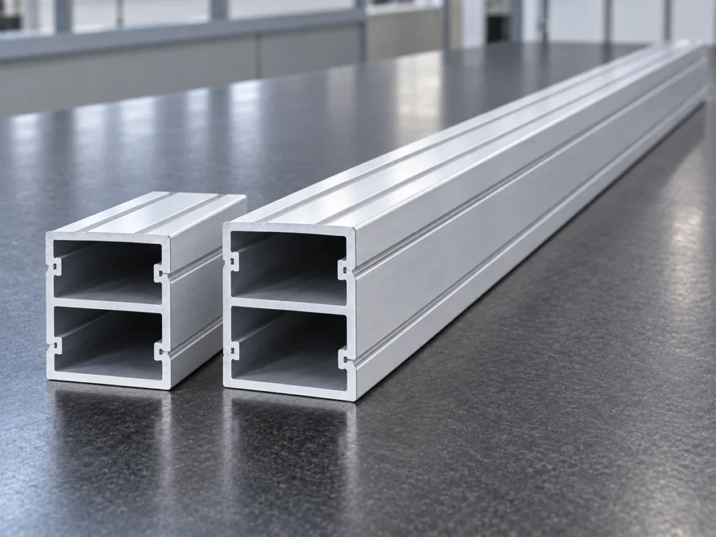
3. Give left and right members separate identities
Extend the fictional project to eight left members and eight right members. Both groups have the same 300 mm blank length. The left member’s finished drawing places its feature on face F2; the right member’s drawing places its feature on face F4, using the defined end-E view.
The cut list contains 16 blanks, but the finished-part list contains two groups of eight. “Sixteen identical finished members” would lose the handed feature definition. Keep the left and right part identities linked to their drawings.
The example describes a document distinction only. It contains no accepted handed design or actual machined parts. A supplier still needs the controlled drawings, tolerances and required feature definitions.
For a mixed aluminum rectangular tube order, list the part identity, quantity, section reference, blank length and later-operation reference together. A shared length can simplify one cutting task while leaving later processing and inspection different.
Use the hole-position drawing guide for the later feature requirements. This article adds the section-view and physical-face references that make the handed distinction readable.

Send one readable handoff
Attach the controlled section view with its viewing direction, the cut-length definition and the separate handed-part list. Identify the end and faces used by later operations. Retain the actual alloy, condition and finish requirements beside those documents.
Our tube-dimension guide covers outside, inside and wall descriptions. Keep those dimensions complete, then use the face and end references here to explain where the finished requirements belong.
Review the defined rectangular-tube cut list
Send JiurunCut the aluminum rectangular tube drawing, lengths and quantities. Show the required stock orientation and identify later operations so the cutting proposal addresses the correct blank and handoff.