
Aluminum extrusion screw slots need a connection review before they become a purchase specification. Confirm the profile feature, fastener family, engagement and delivered condition. A round opening or narrow groove in a section drawing does not identify the screw that belongs there.
Start with the joint you need to assemble. Then connect the extrusion drawing, cutting plan and fastener approval so each supplier works from the same requirement.
On this page
1. Identify the fastening feature
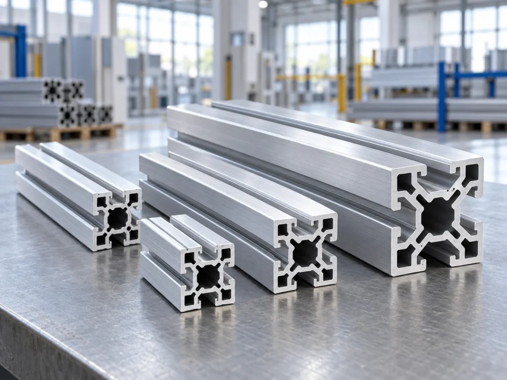
Ask the profile supplier to label the intended connection feature on the cross-section. Specify whether the joint uses an end feature, a machined hole or an external slot with a compatible nut.
Do not let the word “slot” cover every arrangement. A T-slot nut connection is a different purchasing task from driving a fastener into an extrusion-end feature. Use the T-slot nut compatibility guide when a sliding nut is the intended component.
Include a section view and an assembly view. The section view identifies the geometry; the assembly view shows where the fastener enters and which parts it joins. Mark the relevant face rather than asking suppliers to infer it from a product photograph.
Bonnell Aluminum’s design resource includes screw-slot dimensions specifically associated with Type F self-tapping screws. This is a useful reminder to identify the fastening family alongside the feature. It is not a universal size chart for every screw or aluminum section.
2. Choose the thread route
The order should say how the mating thread is created. Is the extrusion supplied with an approved unthreaded feature for a specified direct-assembly screw? Is a hole tapped before delivery? Does the joint use an insert?
Those choices change the supplied condition and inspection request. “Ready for assembly” is too broad when one supplier expects a plain feature and another expects a finished thread.
| Connection route | Information to agree |
|---|---|
| Direct assembly into a specified feature | Fastener identity, receiving geometry, material condition and validated installation requirements. |
| Pre-tapped end hole | Thread callout, usable depth, entry condition and inspection scope. |
| Thread insert | Insert system, preparation, installed condition and acceptance requirements. |
Bossard’s DIN 7500 resource describes thread-forming screws that create a metric thread in suitable malleable material. It identifies material strength, hole geometry, size and engagement length as relevant to installation.
Use the chosen fastener manufacturer’s data for the actual system. Do not apply a steel pilot-hole recommendation or a different fastening family’s dimensions to an extrusion merely because the nominal screw size looks similar.
For supplied threads, refer to the extrusion end-tapping checklist. For an insert system, use the thread insert purchasing guide to keep the preparation and installed component distinct.
3. Mark the drawing clearly
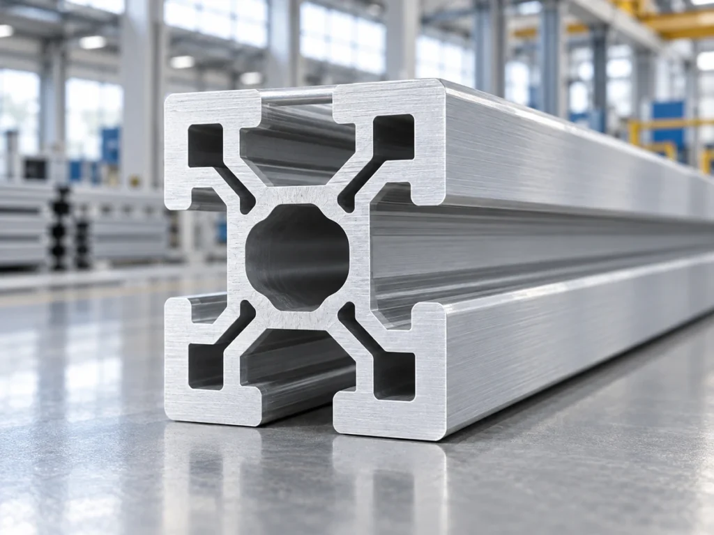
Give the feature its own identifier. Connect that identifier to the mating part, fastener reference and assembly direction. This helps reviewers distinguish a connection feature from a clearance space or unrelated hollow chamber.
Record the profile drawing revision, alloy and temper, intended finish and any secondary machining. Ask the extrusion supplier to review the proposed geometry as part of the complete section, including the surrounding walls.
Keep the functional requirement visible. State what the joint must do, which requirements the responsible engineer will evaluate, and what evidence is needed before approval. A thread label alone does not establish the complete connection’s suitability.
When a plain opening is intended, label it as the receiving feature for the specified fastening system. When a thread is required at delivery, use the actual thread callout and inspection requirement. Avoid mixing those descriptions on the same order line.
4. Connect the cutting and assembly plans
An end connection makes the cut face part of the assembly handoff. Identify the finished length datum, end orientation and the face that meets the mating component.
State the accepted cut-end and edge condition on the drawing. Discuss whether cleaning, edge preparation or secondary machining is included in the supply scope. Keep those operations tied to the actual joint requirements rather than using an undefined “smooth finish.”
Check the assembly drawing for access to the selected fastener and driver. Agree which supplier verifies that access and how the sample will represent the intended installation.
Use the finished-length datum guide to align the cutting and assembly references. A change to the end treatment or mating plate should trigger a review of the affected requirements before recurring production.
5. Review a complete sample joint
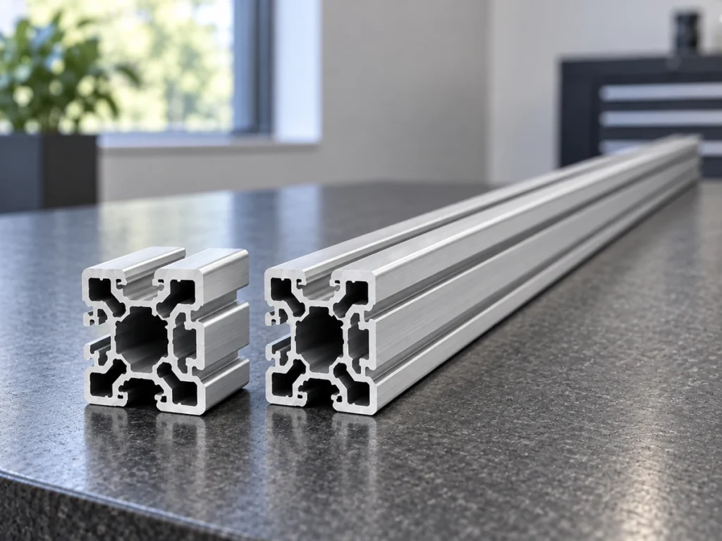
Review the profile, fastener and mating component together. Use the intended material condition, finish and delivered end preparation. Record any differences between the sample and the proposed production parts.
Ask the responsible engineering and quality owners to define the evaluation. Relevant questions include installation consistency, engagement, visible damage, final fit and the joint’s specified functional requirements. Acceptance criteria should come from the application review.
Keep dimensional inspection separate from joint evaluation. A receiving-feature measurement can support the geometry review; it does not replace the agreed assessment of the assembled connection.
Retain the accepted sample identity, drawing revision, component references and report. Use the extrusion sample approval process to connect that decision to later purchases.
Prepare an order request
A concise request can keep the supply scope clear:
Review the identified connection feature on the attached aluminum extrusion drawing. Confirm the proposed fastener system, receiving geometry and delivered thread condition. Identify any required secondary operations. Provide a representative assembly sample and the agreed evaluation evidence before production approval.
For the cutting review, send the cross-section, assembly orientation, finished lengths and quantities through our contact page. Include the joint-related end requirements so the cutting scope can be reviewed against the assembly drawing.
Questions buyers ask
Are aluminum extrusion screw slots the same as T-slots?
Identify the intended fastening arrangement. A slot accepting a compatible nut and an end feature receiving a screw require different component and geometry reviews.
Can any self-tapping screw be used?
Select the exact fastening family and validate it with the receiving feature and material condition. The general term does not establish compatibility.
Should the supplier tap the feature?
Specify whether the approved system requires a supplied thread or forms its mating thread during assembly. Put the delivered condition on the order.
Does a sample that assembles easily prove joint strength?
Assembly fit is one observation. Approve the joint against the functional requirements and evaluation agreed for the application.