
Aluminum profile moment of inertia is a cross-section property used in engineering calculations. In a profile catalog, it commonly appears as Ix and Iy, with units such as cm4 or mm4. It is different from cross-sectional area, section modulus and weight per meter.
For a buyer comparing cut-to-length profiles, the immediate task is to identify the correct catalog field, axis, unit and product variant. This guide explains four common mix-ups so the purchasing description stays aligned with the approved design. It does not select a beam, calculate an allowable load or approve a frame.
Read the label before comparing the number
- Keep the property name and unit beside every value.
- Match the axis to the supplier’s section drawing.
- Preserve the exact profile variant in the order and cutting list.
On this page
Aluminum profile moment of inertia: what it describes
The Engineering Statics textbook describes the area moment of inertia, also called the second moment of area, as a measure of how cross-sectional area is distributed around a specified axis. The distance from that axis is squared in its definition. Its units are length to the fourth power.
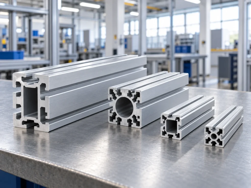
That explains why the full section shape matters. The outside width and height alone do not describe every wall, cavity and groove. A photograph that shows a profile fitting inside a certain envelope does not establish its catalog moment of inertia.
For purchasing, keep the source drawing connected with the data row. If the design team has selected a particular section, reproduce that identity rather than replacing it with a broad description such as “40 mm aluminum.” The data belong to the identified section and its stated axes.
Mix-up 1: comparing different catalog fields
A profile data sheet can place several similar-looking numbers close together. Read the symbol, description and unit as one item. A value in cm2 and a value in cm4 describe different quantities; numerical closeness does not make them interchangeable.
| Catalog field | What to preserve |
|---|---|
| Area, A | The section area and its square-length unit. |
| Area moment, I | The specified axis and fourth-power unit. |
| Section modulus, W | The specified axis and cubic-length unit. |
| Mass per length | The mass unit and the length basis. |
A real example is item’s Profile 8 40×40, natural data sheet, article number 0.0.026.03. It lists area as 9.16 cm2, Ix and Iy as 13.96 cm4, Wx and Wy as 6.98 cm3, and mass per length as 2.47 kg/m. These figures describe that catalog article, not the illustrative images here.
The example is useful for reading the columns. It is not a recommendation to use that profile for a particular load. If a purchasing spreadsheet has one field called “profile strength,” replace the ambiguity with the actual requested property name and source reference.
For material quantity planning, follow the profile-weight calculation guide. Keep that calculation separate from a section-property comparison. A kg/m value should not be copied into a field requesting Ix.
Mix-up 2: losing the axis information
Ix and Iy identify different axes. Use the axes drawn on the supplier’s section drawing. Do not assume that the page’s horizontal direction, a photograph’s orientation and the installed profile’s orientation all correspond to the same catalog label.
If a comparison sheet shows only “I = 20,” it is incomplete. Ask which property, which axis, which unit and which profile article the number describes. Keep a small section drawing or a clear source reference beside the value so a reviewer can interpret it without guessing.
Where the two axis values differ, copying only the larger one hides information. Where they are equal, retain the axis labels anyway. Equal values in one data sheet do not establish the same relationship for every product with similar outside dimensions.
A cutting order should preserve any required orientation in the part drawing. End angles, visible faces or later machining features can make orientation relevant even when the stock description looks symmetric. The mirror-image part guide shows why orientation and part identity deserve their own fields.
Mix-up 3: converting fourth-power units as ordinary length
A moment-of-inertia unit includes a fourth power. Since 1 cm equals 10 mm, 1 cm4 equals 104 mm4, or 10,000 mm4. Multiplying by 10 converts length; it does not correctly convert this section property.
For the catalog example above, 13.96 cm4 converts to 139,600 mm4. This is a unit conversion of the published value, not a new calculation from measured profile dimensions. The axis and product identity stay the same.
A fictional comparison makes the issue clearer. Suppose one record says Ix = 20 cm4 and another says Ix = 200,000 mm4. After conversion, the two numbers are equal. That equality alone does not establish that two stock products are interchangeable.
Use separate columns for the original value, original unit and converted value. Keep the original source available for review. This makes it easier to distinguish a genuine property difference from a spreadsheet conversion error.
Mix-up 4: using data for a different profile variant
A shared outside size is not a complete product identity. Check the exact article number, section drawing and variant description. A changed groove arrangement or internal cavity can mean that the selected data sheet no longer describes the offered stock.
When a supplier proposes an alternative, ask for its own technical data and section drawing. Put the original and proposed identities beside each other. The reviewer can then decide whether the alternative meets the full design requirement rather than relying on a matching width and height.
Do not invent section-property values from the illustration or average figures from neighboring catalog rows. If data are missing, identify them as missing and request the correct source. A clean blank field is easier to resolve than a plausible number with no traceable basis.
From design selection to a cutting order
item’s technical profile guide uses moment of inertia together with material modulus, free length and a defined loading arrangement in its deflection equations. This shows why an I value by itself is not a complete frame-performance answer. The assembly requires its own engineering review.
Once the approved profile is identified, the cutting order still needs the finished length, end-angle convention, quantity and relevant part revision. State these directly. A correct catalog row does not define where the saw-cut length is measured or which end features the customer requires.
For a machine review, send the actual section drawing and intended cutting orientation. Review them through the cutting-capacity drawing guide. A profile’s area moment of inertia does not establish that it fits a machine’s cutting envelope or fixture arrangement.
Buyer questions
Is moment of inertia the same as weight per meter?
No. Keep the catalog labels and units separate. Weight per meter supports mass planning; the area moment of inertia describes a cross-section about a stated axis.
Can the same outside size have different section data?
Yes. Use the exact variant’s drawing and data sheet rather than assuming the outer envelope identifies the complete section.
Does a larger I value prove that a complete frame is acceptable?
No. A section-property comparison does not replace the review of the actual assembly, loading, supports and applicable requirements.
Bring the approved section into the cutting review
Send JiurunCut the identified profile drawing with cut lengths, end angles and batch quantities. Keep catalog properties linked to the exact stock identity so the machine discussion starts with the intended section.