
Aluminum T-slot nut compatibility needs the profile and fastener identities together. The bolt’s thread size is only one part of the connection. Check the supplier’s profile series, slot geometry, nut design and approved assembly method before treating hardware as a match.
For a cut-profile order, this review also affects the manufacturing handover. The receiving team needs the right profile family and usable access for its selected connection. Five checks turn a vague hardware request into information that a profile supplier, assembler and cutting-machine supplier can review.
Keep these identities together
- The profile supplier, series and part number.
- The nut part number, body design and complete thread designation.
- The approved connection and how the hardware enters the slot.
On this page
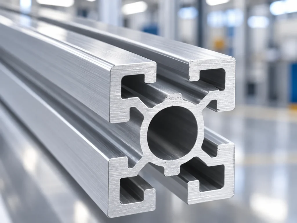
Start with an incomplete request
Imagine a fictional inquiry that says: “Supply M8 nuts for a 40 mm aluminum profile.” No particular supplier or job is implied. The request gives a thread label and an outside profile size, but leaves several questions unanswered.
Which supplier’s profile is it? Which profile part number and slot are involved? What nut body and insertion method are required? Which mating fastener and connector complete the intended joint? An answer to one of these questions does not automatically answer the rest.
For example, 80/20 lists an M8 double slide-in nut in its 40 Series and an M8 self-aligning roll-in nut in its 45 Series. The nominal thread label appears in both product names while their product and series descriptions differ. This supports asking for the full identity; it does not establish whether either nut fits another supplier’s profile.
Check 1: identify the profile for aluminum T-slot nut compatibility
Record the profile manufacturer, series, part number and applicable drawing. Include the actual section used in the cut list. A broad description such as “industrial extrusion” cannot establish the fastener interface.
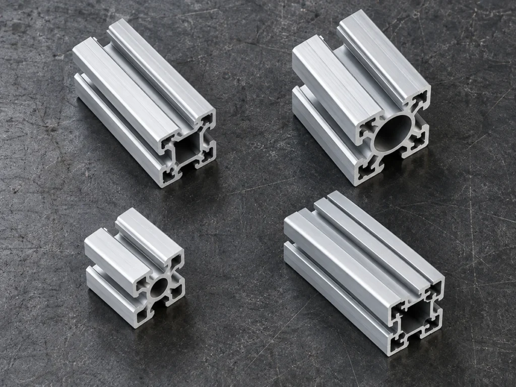
Do not turn an outside dimension into a compatibility rule. Profiles with similar external sizes can require review of their own slot and internal geometry. Metric and inch-based labels also need their actual drawings and units, rather than a visual size comparison.
If the project contains several profile families, list the connection hardware against each relevant identity. This lets procurement see where one hardware item is specified for more than one member and where different items are required. Retain the supplier’s documented compatibility statements.
For the broader cutting route, the T-slot frame-planning guide connects profile identity, finished lengths and connector preparation. Use this nut review as the detail behind the slot-hardware part of that plan.
Check 2: review the slot and nut body
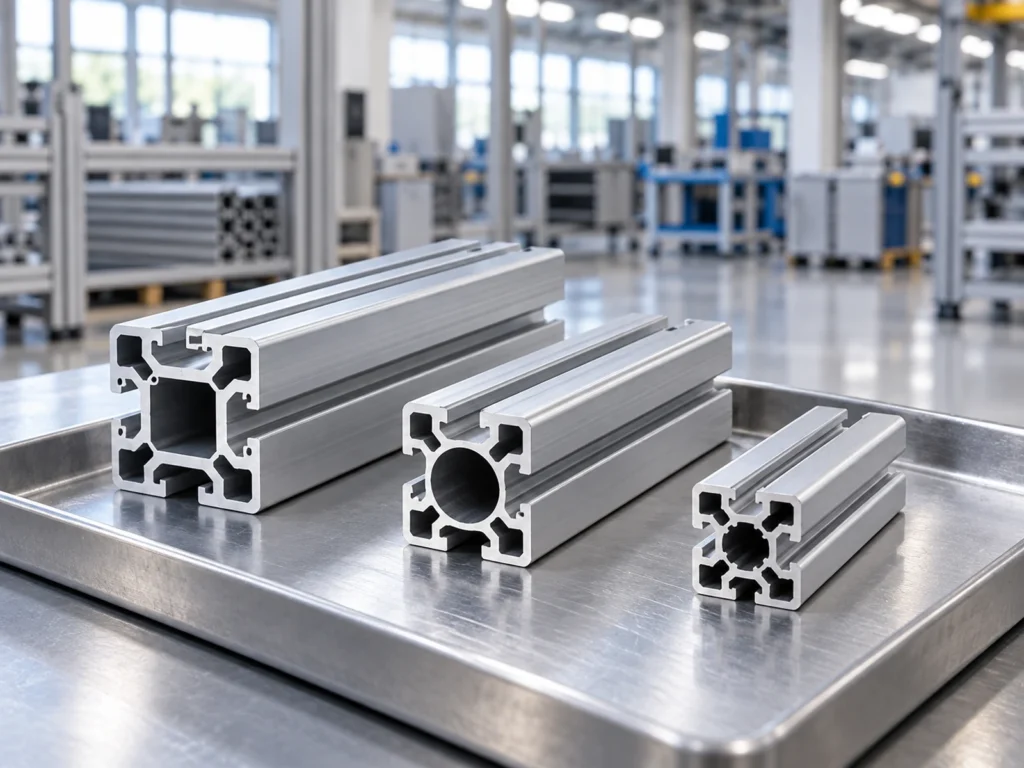
Use the profile and nut drawings to review the mating geometry. The visible slot opening is one relevant feature, but the internal space and the surfaces that support the nut also matter to the approved connection. A single width measurement cannot replace the complete interface review.
Ask the hardware supplier to confirm the intended profile application for the exact nut. Provide the actual drawings when mixing supplier systems or reviewing a substitute. Avoid approving a match solely because the body can be placed inside a loose profile sample.
Keep the manufacturer’s body style and part number in the purchase description. Similar names can cover different shapes, alignment features or retention arrangements. The receiving team needs an identity it can check against the order.
Check 3: match the complete thread and mating fastener
Specify the thread designation required by the approved connector and fastener. Confirm the intended thread form and pitch from the component documentation. Do not substitute a metric or inch fastener because its diameter appears close.
Separate the threaded interface from the nut-to-profile interface. A bolt can match a nut’s thread while the nut body still needs confirmation against the profile. Conversely, a documented nut body match does not identify the correct mating bolt by itself.
Review the complete connector stack through its approved documents. Brackets, plates and other parts affect the specified fastener arrangement. Use the supplier’s instructions for the intended connection rather than prescribing a universal bolt length or tightening value.
Check 4: review how the hardware enters the slot
Ask whether the chosen nut is installed through an accessible profile end or by the method specified for its particular design. Slide-in and roll-in product descriptions identify different hardware styles, so keep the intended style visible in the purchase and assembly documents.
Look at the assembly stage where the nut is fitted. A profile end that is accessible before assembly may later be covered by another member or component. Confirm the planned sequence with the assembly team while there is still time to clarify the hardware choice.
Use the actual manufacturer’s instructions to decide the insertion and positioning method. This article does not provide a substitute assembly procedure. The useful buyer question is whether the selected hardware can be installed as intended at the specified stage.
If the frame may need later accessories, describe that requirement separately. Ask the system supplier which approved hardware and access arrangements cover it. Avoid assuming that every nut style can be added anywhere after the frame is complete.
Check 5: connect the cutting and assembly handover
Preserve the profile identity through cutting, sorting and packing. The assembler needs the specified slot family as well as the correct member length. Keep a change in profile supply visible so its effect on the hardware can be reviewed.
State the agreed cut-end, edge and cleanliness requirements relevant to the next stage. Identify any additional connector features that must be created after sawing. Cutting to length does not create a threaded end hole or other machining feature by implication.
Discuss surface protection for the profile and the intended connection. The surface-handling guide can support the cutting-stage discussion. The assembly team still needs the component supplier’s applicable connection requirements.
Where members and hardware are delivered as sets, reconcile both against the approved list. The frame-kit review helps distinguish a pile of cut members from the identities and components required for a complete set.
A clearer inquiry brief
Replace the fictional one-line request with a brief that names the information to be confirmed. The following fields are a planning template, not an approved component specification.
- Profile: supplier, series, part number and section drawing.
- Nut: exact part number, body design and thread designation.
- Connection: mating fastener, connector identity and applicable instructions.
- Access: assembly stage and the approved insertion method.
- Cut members: drawing revision, lengths, quantities and preparation scope.
Send the connection review to the responsible profile or hardware supplier. For machine selection, share the actual extrusion drawing and cutting requirements with JiurunCut. Explain the later connector preparation and handover needs so the cutting proposal addresses the intended stock.
Buyer questions about T-slot nut selection
Does an M8 label identify the correct T-slot nut?
No. It gives a nominal thread identity, while the nut body, profile application and complete connection still need confirmation. Use the exact component documents.
Can I use the profile’s outside size to choose the nut?
Use the supplier’s profile identity and interface information. Outside size alone does not establish the internal slot geometry or an approved hardware match.
Does a loose sample fit confirm connection performance?
It can help inspect an interface question, but it does not establish the approved connection or its application rating. Keep those decisions tied to the actual system documentation and review.