
Aluminum frame kits need a cutting plan that preserves the identity of each member and the number of complete sets required. A pile of correctly cut pieces can still leave assembly waiting when one length, orientation or part variant is missing.
For a machine inquiry, describe the kit as a defined set of parts. Then connect the set to the profile drawings, cutting list, inspection records and delivery sequence. These five checks help buyers discuss a production job in terms of usable sets as well as individual pieces.
Three counts to keep separate
- Planned pieces: each member quantity required by the current parts list.
- Accepted pieces: identified members that have completed the required checks.
- Complete sets: the correct combination of members for each defined kit.
On this page
1. Define what the aluminum frame kits contain
Give the kit a part-list identity and revision. State whether it contains only cut profile members or also includes machined members, connectors, panels and other components. A “frame kit” can mean different supply scopes to different teams.
Keep the cutting scope visible within that larger list. A saw-cut member may still require drilling, tapping, finishing or another operation before it belongs in the released assembly set. Identify those stages without assuming that the cutting machine performs them.
For an industry reference, Bosch Rexroth’s aluminum profile system overview describes profiles, connectors and accessories and shows tools that generate parts lists. It illustrates the difference between a profile line item and a complete construction. It does not prove compatibility with an unspecified profile or JiurunCut equipment.
Use an assembly drawing alongside the individual member drawings. The assembly view explains where parts belong; the member drawing defines what the cutting and downstream work must produce.
Have the responsible designer confirm the connection system and structural requirements. A cutting plan cannot establish frame loading, fastening suitability or compliance from an image of a corner.
2. Give each member a complete cutting identity
Use a separate line for each distinct finished member. Record its part number, profile identification, material description, length convention, end requirements and quantity per kit. Include the drawing revision used for the line.
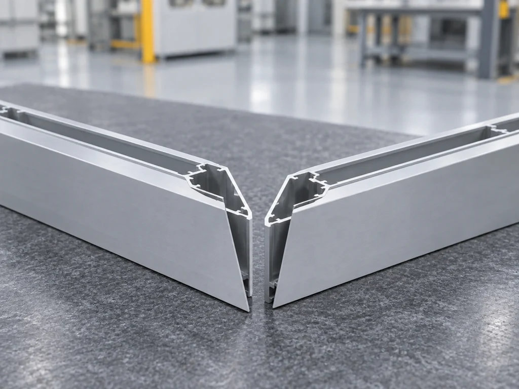
For angled ends, show the required orientation in identified views. Two members with the same numeric length may still have different end arrangements or handed features. Do not merge them merely because their lengths match.
Keep the finished length definition consistent. Identify the relevant long point, short point, reference face or drawing datum. Use the finished-length datum review to make that decision explicit.
Separate finished dimensions from stock dimensions and allowances. If a member requires later machining, state which operation establishes its final feature. The cutting list should not silently replace a finished-part drawing with an approximate blank size.
The item Engineeringtool documentation overview lists parts lists, machining plans, dimensioned views and assembly guides as project documentation. These are useful categories to request from your own design team; the reference does not establish a JiurunCut software integration.
Ask how the proposed machine workflow handles distinct members, end orientations and job changes. A reviewed cut-list file is useful only when its fields preserve the required part identities.
3. Convert kit demand into member demand
Start with the quantity per kit, then multiply by the planned number of kits for each member line. Keep optional spares and trial pieces on separate lines so they do not inflate the number of customer sets.
After inspection, reconcile accepted quantities by member identity. Total accepted pieces alone do not show how many complete sets can be formed. The member with the smallest available quantity relative to its per-kit requirement limits the count-based completion.
Where parts are matched, have different variants or cannot be interchanged between sets, retain those restrictions. A simple quantity calculation cannot override an approved matching requirement.
A twelve-set planning example
This fictional example concerns only two interchangeable profile-member types. Each defined set needs two long members and two short members. It excludes connectors, panels, assembly work and any matching restriction.
| Member requirement | Twelve-set plan and accepted count |
|---|---|
| Long members: two per set | Plan: 24. Accepted: 23. This supports 11 whole sets by count. |
| Short members: two per set | Plan: 24. Accepted: 24. This supports 12 whole sets by count. |
The plan contains 48 members. The accepted total is 47, but those quantities can form only 11 complete profile-member sets: 22 long and 22 short members. One accepted long member and two accepted short members remain outside those 11 sets.
One more accepted long member would resolve this count shortage if every other required condition is satisfied. Extra short members cannot replace the missing long member. The calculation is not a machine-output claim or evidence of assembled-frame acceptance.
Report the shortage by its member identity. This gives planning a useful next action instead of a summary saying “almost all pieces finished.”
4. Preserve identity through sorting and handover
Choose how members will be grouped after their required checks: by member type, by complete set or by the agreed assembly sequence. The useful arrangement depends on what the receiving team needs to do next.
If members are stored by type, keep the set-completion record alongside the quantities. If they are grouped into individual sets, identify the set and its contents. Avoid a package label that only states a total number of aluminum pieces.
Keep part markings and packaging requirements tied to the surface specification. Ask the responsible team to approve marking locations and protective materials where appearance or later processing matters. Do not assume any adhesive label or spacer is suitable for every finish.
Make unresolved parts distinguishable in the records. A member awaiting inspection, additional work or a decision should not quietly count toward a released kit.
For staged deliveries, define whether the receiver wants complete sets or a named member batch. Either arrangement can be planned, but the dispatch record should say which one has actually been supplied.
5. Review a representative member set
A cutting trial should include the member differences that matter to the job: profile families, lengths, end arrangements and any difficult handling requirements. Confirm the samples and required records before the trial begins.
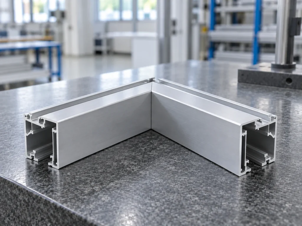
Identify each trial member and inspect it against its own drawing. Where the job requires assembly-fit review, use the approved components and assembly method. A visually neat corner is not a complete dimensional or structural assessment.
Keep individual-part checks separate from the assembly review. Your frame diagonal check can form one part of the required plan, while member dimensions and connection requirements remain separately defined.
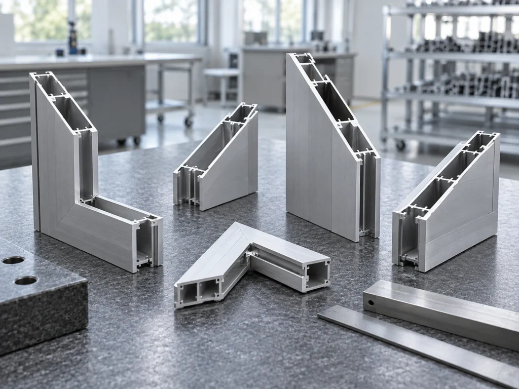
Use the trial discussion to identify sorting, recording and handover needs for the proposed production workflow. Do not translate a displayed set of samples into an unverified kits-per-hour claim.
Prepare the cutting-machine inquiry
Send the assembly drawing, current member list, profile drawings, material descriptions and planned kit mix. State the required quantities per member, the number of sets and the intended delivery or assembly sequence.
Identify which work belongs to cutting and which work occurs later. Add the critical inspection features and any approved matching rules. This gives the machine review a clear job scope instead of a general request to “cut a frame.”
Ask JiurunCut to review the member list and cutting requirements. Confirm the proposed machine workflow against the actual parts, available documentation and representative trial needs.
Buyer questions about aluminum frame kits
Does a total piece count show the number of complete kits?
No. Count accepted members by identity and compare each quantity with the requirement per set.
Can equal-length members be combined into one cutting-list line?
Only when their complete finished-part requirements are identical. Check profile, orientation, end details and revision before combining them.
Does cutting all members mean the kit is ready for assembly?
Not if required downstream work, inspection or other kit components remain incomplete. State the actual release stage.
What makes a useful initial inquiry?
A current member list connected to the assembly and part drawings, with set quantities, cutting scope and acceptance requirements clearly identified.