
A thin-wall aluminum profile needs support and clamp contact that suit its actual section. Identify reinforced areas, cavities and visible faces before selecting a saw. These five checks help you discuss stable location, contact marks and sample inspection without guessing a universal clamping pressure.
Three things to remember
- Start with the actual end-view drawing or a physical sample.
- Specify which walls and faces may contact the fixture.
- Judge the finished piece, not just the machine’s quoted accuracy.
On this page
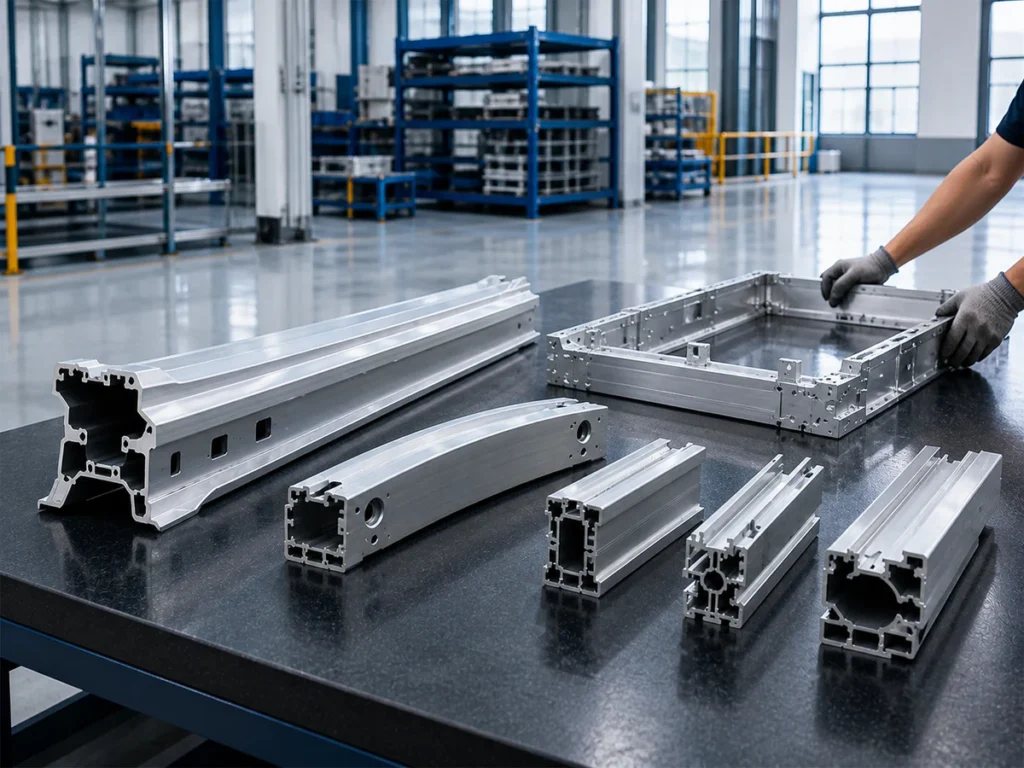
1. Read the thin-wall aluminum profile section
Two profiles with the same outside width can have very different webs, voids and wall thicknesses. A clamp that bears on a reinforced area of one profile may mark or move the unsupported wall of another.
Give the machine supplier the section drawing and explain which faces are functional, decorative or hidden after assembly. This lets the discussion move from generic clamp pressure to actual contact geometry.
- Cross-section and wall locations
- Critical visible faces
- Permitted contact and support surfaces
Mark the contact zones on a section drawing. Show where a fixture can bear against a reinforced area and which faces must remain acceptable. Include the shortest and longest finished parts in the trial. For a thin-wall aluminum profile, inspect shape and contact marks after removal from the fixture, so the review includes both holding and collection.
2. Review support before and after the cut
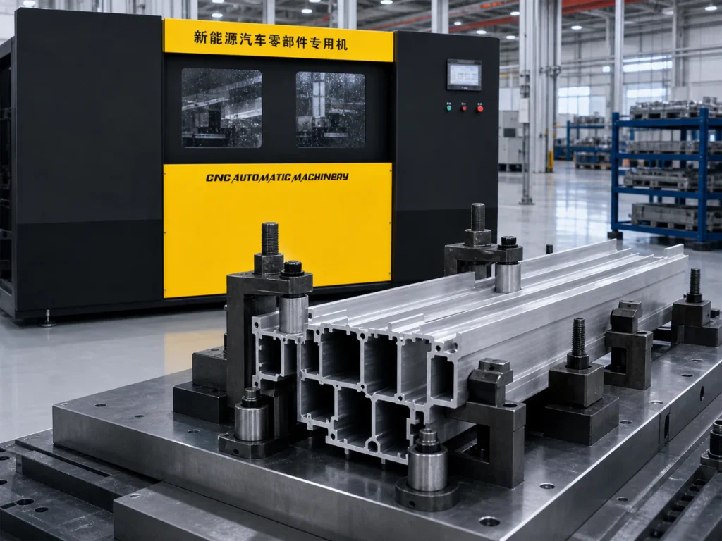
The stock should stay located as the blade enters and exits. Review the fixed and moving supports, the distance from the cut to the nearest support and the path of the finished piece after separation.
A short sample can look acceptable while a longer or more flexible piece behaves differently. Include length extremes in the sample plan and note whether the operator changes any supports between them.
- Shortest and longest finished part
- Where the cut piece lands
- Any unsupported span during feeding
3. Separate clamp marks from cutting defects
Inspect more than the cut face. Check the profile outline, the faces that touched the fixture and the surfaces that will meet another component. Agree on the reference drawing and inspection method before the test.
If a sample is unsatisfactory, record whether the issue appeared during feeding, clamping, sawing or collection. That distinction helps engineering teams adjust the correct part of the process instead of changing the saw blindly.
- Profile deformation
- Contact marks
- Cut-face and assembly-fit observations
Contact location
Information to send: End-view and marked surfaces
Question to ask: Which webs or base areas can safely carry the fixture contact?
Finished part
Information to send: Length range and use in assembly
Question to ask: Does the sample retain the required shape and fit?
Changeover
Information to send: All profile families in the job
Question to ask: Which supports or fixtures change between families?
▶ Watch: Extrusion Supports & Clamps
This video shows a machine setup example. Confirm the configuration against your own profile drawing and sample.
4. Plan fixture changes for each family
If production includes several thin-wall sections, request a fixture plan for each family. Record the changeover steps and how the operator verifies the first part after a change.
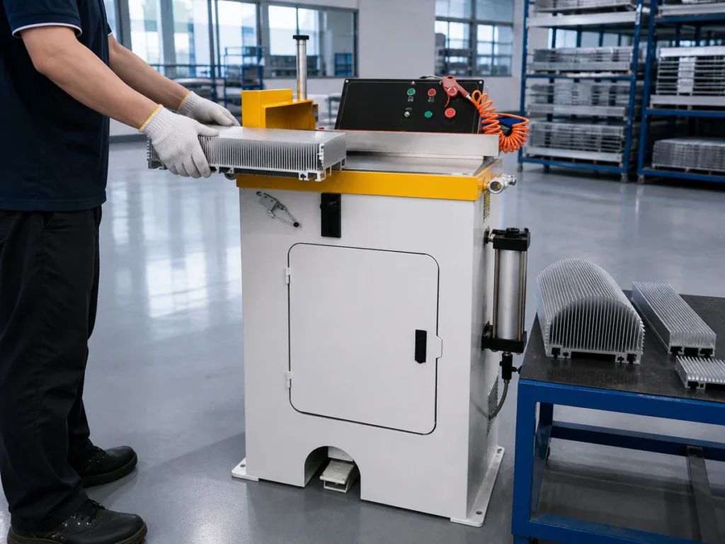
A claim that one machine cuts many profiles does not mean one clamp arrangement suits every profile. The thin-fin heat sink guide illustrates why fragile geometry needs its own support review.
5. Send the information needed for a recommendation
A drawing, stock photo and one representative sample are more useful than an unsupported request for a particular clamping force. Include the finished lengths, angles, quantities and the issue you are trying to avoid.
JiurunCut can discuss a suitable machine direction after reviewing the part. Explore the aluminum profile cutting machine page for the product family, then use the inquiry form to share your section.
Common questions
Is lower clamp pressure always better?
No universal pressure suits every section. The part still needs stable location; evaluate the actual fixture and sample result.
Can a drawing replace a physical sample?
A drawing starts the review. A representative sample helps verify contact marks, shape and cutting results under the proposed setup.
Should I ask for a guaranteed tolerance first?
Start with the finished-part drawing and measurement method. Any tolerance discussion needs the part, material and setup conditions.
Discuss your cutting requirements
Send your thin-wall aluminum profile drawing, stock length and finished-part range. Mark functional and visible faces, and show the defect you need to avoid. We can review the section and discuss the supports, fixture and sample checks needed for a useful recommendation.
References and scope
This article describes an engineering review method, not a set of operating instructions or a guaranteed clamp design. Recommendations require a review of your drawing, sample and production requirements.