
A wardrobe sliding door track order can arrive as a single line on a cutting list: “track, cut to width.” That line does not tell the saw operator which extrusion is the upper runner, which is the lower guide, or which end must remain open for a fitting. The useful first step is to separate the parts of the actual system before anyone releases lengths.
This matters because the cut is only one operation in a fitted door system. A straight aluminum extrusion can leave the saw with a clean face and still be the wrong component, the wrong orientation, or the wrong length for the approved cabinet layout. The installer or system designer must confirm the installed travel and hardware positions; the cutting supplier can then work from an identified profile and a controlled datum.
What belongs on a wardrobe sliding door track cut list?
Ask for the maker’s part reference, drawing revision, and a photo or sample of each extrusion. A runner and a guide may be sold together while doing different jobs. For example, Hettich’s TopLine XL profile set lists separate aluminum runner and guide profiles and their respective mounting clips. That is one named product example, not a dimension or hardware specification for every wardrobe system.
Mark the extrusion that the door mechanism runs on and the extrusion that guides the door. Then identify any covers, clips, stops, or other supplied pieces on their own lines. Do not treat a kit’s stock length as a finished cabinet cut length. If the customer sends only a photo of an assembled wardrobe, request the individual profile reference and the approved installation drawing before setting a stop.

Decide what the length measures
“Cabinet width” can mean the outside width of the carcass, the clear opening, or a dimension to a finished face. None of those should silently become the saw length. The drawing should identify the installed start and end points for each runner and guide, and say whether the quoted length includes any clearance or allowance required by that specific system.
Choose a repeatable measuring face on each extrusion. On an asymmetric section, the visible front edge, mounting flange, and track channel are not interchangeable datums. Put a simple arrow and “left/right” or “front/back” on the approved sample. The same marks should appear on the cut list so that a mirrored part cannot be accepted merely because its overall length is correct.
Check the end condition as well. A square cut may be appropriate for one installation, while another system may require an end stop, cap, access opening, or a later operation. The cutting instruction should state which end is finished at the saw and which end is intentionally left for fitting. The system maker’s instructions and the installer’s approved layout govern the answer.
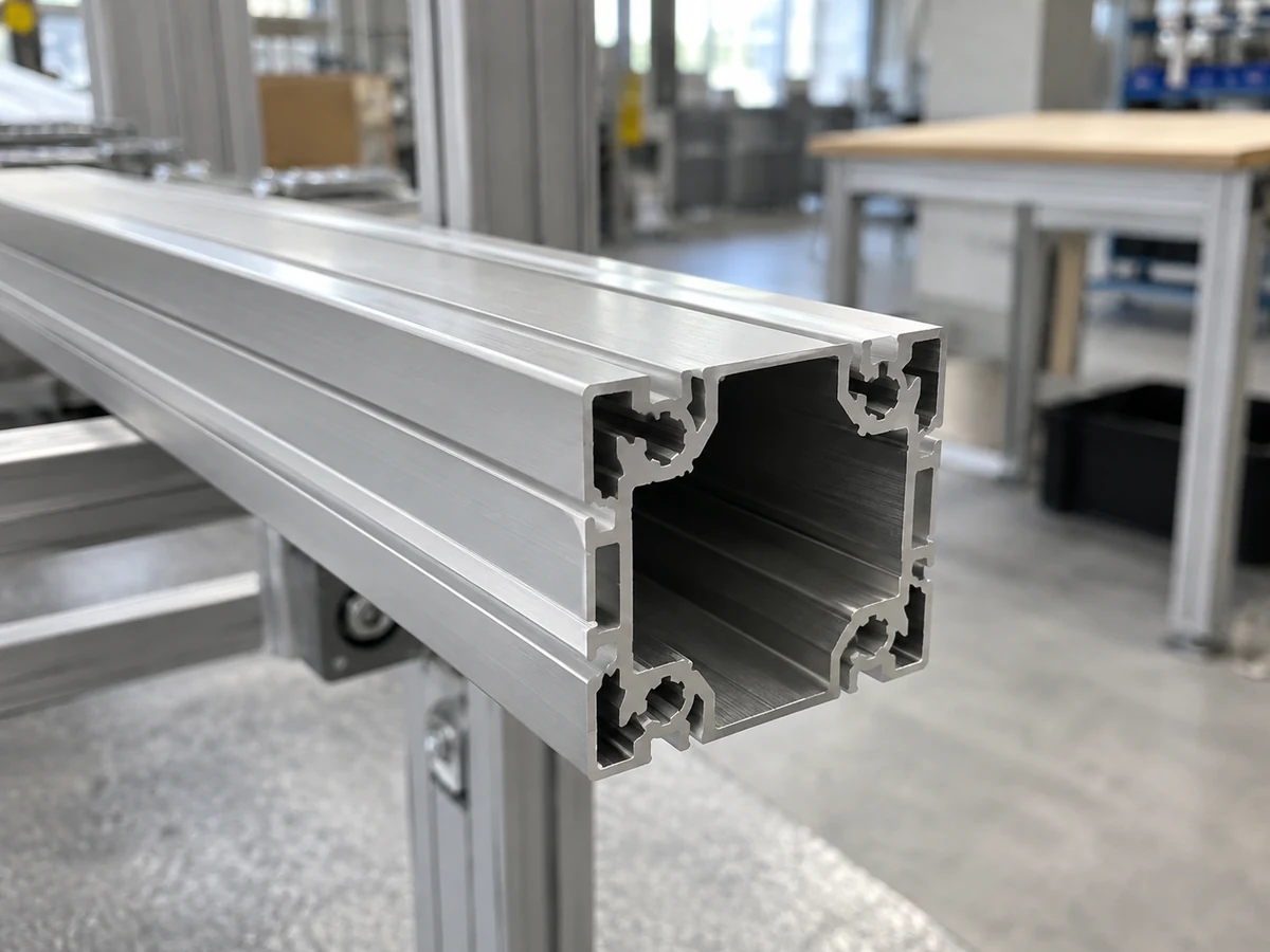
Keep the clips and travel out of the saw assumption
Clips, fasteners, and door stops can govern where the extrusion sits in the cabinet, but their positions are an installation decision. The saw operator should not infer clip spacing or travel limits from an extrusion photo. Obtain the manufacturer’s installation instructions and the project drawing, then identify any areas where a clamp or stop on the cutting machine could contact a finished surface or an open channel.
A practical release sequence is to label each physical profile, compare it with the drawing, mark the datum and orientation, and approve one first-off piece from each distinct section. The first-off check should record the measured length, end face, visible surface, and any feature that matters to the next assembly step. If the assembly relies on a clip or stop at an end, check that interface against the actual system hardware before releasing a batch. A photo of a clean cut face alone cannot validate door movement.
Where an automatic profile saw fits
An automatic saw may help feed and cut repeated straight aluminum sections once the component identity, cut length, orientation, and support method are approved. The job still needs a suitable fixture and an agreed inspection method for that extrusion. This article does not claim a particular tolerance, output rate, or compatibility with a named wardrobe system.
The Jiurun Machinery channel video below shows an automatic straight-profile feeding and cutting scene. It is an equipment illustration only. It does not show this Hettich system, a wardrobe installation, a customer order, or a performance test for the profiles described here.
The buyer’s release package
Before requesting a production quote, send the supplier four things: the maker’s profile references for runner and guide; a section drawing or sample showing the measuring face and orientation; a cut list tied to the approved cabinet drawing; and the end-condition and first-off acceptance criteria. Include the expected batch quantity and whether parts arrive as stock extrusions or within a hardware kit. Ask the cutting supplier to flag any surface, channel, or section that needs special support.
If the system drawing is unavailable, order a sample cut for identification and fit review rather than treating the sample as proof that the assembled door will travel correctly. The final release belongs to the party responsible for the wardrobe system and its installation.
For a discussion of straight aluminum profile cutting equipment and how to prepare representative pieces for a trial, contact Jiurun Machinery with the approved profile reference and drawing. We can review the cutting setup against the actual extrusion supplied.