
Thread depth vs hole depth is a distinction between two features. The specified full-thread extent does not describe every part of the hole, and a hole-depth value does not identify how far the accepted thread extends.
For an aluminum component, connect both values to the controlled drawing. Identify their start reference, the affected hole and the required supplied stage before comparing machining quotations.
Four checks for an understandable callout
- Separate the full-thread requirement from the hole requirement.
- Identify the face or plane each depth starts from.
- Define the hole’s end condition and relevant bottom geometry.
- Assign the two feature checks to the delivered component.
On this page

1. Separate the fields for thread depth vs hole depth
Start with the component’s full thread designation and the specific feature reference. Locate the required threaded extent in the drawing rather than reading it from a general hole-depth field.
Keep the hole’s own extent as a separate requirement. Where the drawing supplies both, preserve the original labels, units and limits in the quotation comparison.
Onshape’s primary Hole documentation provides a useful field distinction. It lists Depth for a blind hole and Tapped depth for the full-thread depth of a tapped hole. It also has a separate tap-clearance field. These describe software feature definitions, with no automatic approval of a manufacturing allowance for your part.
Ask the drawing owner to resolve a callout that uses only the word depth. Identify which extent is controlled and what feature its limit refers to before assigning it to the machining supplier.
Keep the thread designation attached to its depth requirement. A confirmed axial extent does not supply a missing thread size, pitch, hand or specified class.
For a profile member, our extrusion end-tapping guide covers the end identity and operation count. The particular hole still needs its own complete feature definition.
2. Name the face or plane that each depth starts from
A depth value needs an origin. Identify the relevant entry face or other specified plane in the controlled section view. Keep that reference alongside the stated extent.
Onshape’s documentation distinguishes starting a hole from the part, a sketch plane or a selected plane. That distinction illustrates why the number alone does not locate the feature’s start.
For your actual drawing, preserve its specified reference rather than adopting a software default. If the depth starts from a recessed face or another defined level, make that relationship visible in the approved detail.
Do not transfer a depth from one face to another when comparing drawing revisions. Ask which reference changed and which dimension is intended to remain controlled.
If an entry recess is specified, retain its own dimensions. Resolve whether a stated overall hole depth includes the recess within that drawing’s definition. An unlabelled subtraction can change the meaning of the requirement.
For several holes on different surfaces, give each shared requirement a clear grouping. Similar written depths do not mean every hole begins at the same position.
A receiving record should identify the same origin used by the acceptance requirement. Keep the method and feature reference with the result so the quality team can follow what was checked.
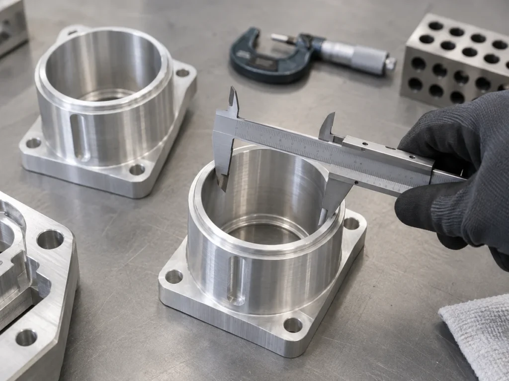
3. Read the end condition and relevant bottom geometry
Identify whether the hole terminates at a stated blind depth, continues through the identified material or ends at another specified boundary. Retain the end definition in the quotation and supplied-part drawing.
Keep any relevant bottom or tip geometry in the section detail. A drawing may distinguish the extent of a diameter from the furthest point of an end shape. Ask the responsible designer to make the intended endpoint explicit.
The Onshape reference separates hole termination options from its tip-angle settings. It also distinguishes a custom tapped depth from a through-thread option. These categories help organize the review without choosing an actual tool, angle or depth.
A through hole does not, by its name alone, state the required threaded extent. Read the controlled thread callout and preserve any specific end or extent requirement.
Where an actual design needs space beyond the full thread, ask the responsible design and machining teams to define it. This article provides no standard extra depth, pitch multiple, drill-point allowance or tapping setup.
Keep tool and process planning distinct from the product requirement. The machining supplier can explain how its confirmed process addresses the actual controlled feature, while the approved drawing remains the acceptance reference.
4. Agree the accepted feature at the supplied stage
State whether the quotation covers a cut blank, a drilled component, a tapped component or another completed stage. A drilling-complete record does not establish that the thread requirement has been accepted.
Assign the required checks for each distinct feature. Keep the hole extent and full-thread extent identifiable even when the same supplier performs both operations.
Ask the responsible inspection team to specify a checking method appropriate to the actual requirement. Retain the component identity, drawing revision, feature reference and supplied condition with the result.
Our thread-gauge and caliper comparison explains why a checking tool must answer a defined requirement. A broad thread-pass statement should not be treated as evidence for an unspecified depth check.
Keep a dimensional result, a thread check and an assembly review as separate records when the approved plan requires them. Each establishes evidence within its own stated scope.
For a proposed substitution or changed process, ask which feature requirements and records remain applicable. Resolve any change in the delivered stage before treating two quotations as equivalent.
A fictional quotation review with two required extents
Imagine fictional feature H1 on an aluminum component. Its controlled drawing specifies a hole extent of 18 mm and a full-thread extent of 12 mm, with both starting references explicitly identified.
A supplier replies “hole depth 18 mm” without confirming the threaded extent. That response addresses one field and leaves the other open.
| Specified field | Response status |
|---|---|
| Hole extent: 18 mm | Supplier identifies this field in its response. |
| Full-thread extent: 12 mm | Confirmation and applicable acceptance record remain open. |
Ask the supplier to confirm the full-thread requirement against the same drawing revision and identify the supplied stage. Keep the two responses together so the receiving team can see what each establishes.
These invented values are not recommended drilling or tapping dimensions. Their difference is not an approved clearance or a complete process plan. The example only explains how one confirmed field can leave another unresolved.
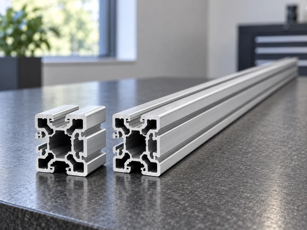
Read the model and drawing together
Check the model and drawing against the same component revision. Keep the full-thread and hole-depth definitions visible in the controlled manufacturing documents.
Onshape describes cosmetic threads as visual representations that do not change the geometry. For a model using that representation, the visible hole shape alone does not carry all the thread requirements.
Ask the model owner to preserve the applicable feature and drawing information when handing the part to another system or supplier. Resolve missing annotations before accepting the exported view as a complete specification.
Keep the fastener’s dimensions separate from the receiving hole’s requirements. Our screw-length and thread-length guide addresses the supplied screw. Its threaded portion does not automatically define the aluminum component’s accepted full-thread depth.
Questions to close before ordering
Does the hole-depth value establish the full-thread depth?
Read and confirm the distinct thread requirement in the controlled drawing.
Does a through hole require a through thread?
Keep the thread extent explicitly specified for the actual component.
Can a bore photograph prove a finished threaded feature?
Use the drawing and applicable feature records. The illustrations here supply no accepted depth or thread result.
Separate the cut blank from later hole processing
Send JiurunCut the actual aluminum section, cut dimensions and required supplied stage. Keep thread depth vs hole depth clear in the downstream drawings and quotation scope.