
Spotface vs counterbore concerns the mounting feature the drawing needs. A spotface provides a flat mounting surface around a hole. A counterbore provides a flat mounting surface within a cylindrical recess.
For an aluminum component, identify the intended seat and mating hardware. Then retain the complete geometry required for that assembly.
Start with the assembled section
Mark where the mating component contacts the part and where it must sit relative to the surrounding face. Keep that requirement visible in the section view.
A top-view circle can leave the reader uncertain about the seat and recess. Ask the drawing owner to clarify the intended feature before the machining provider quotes it.
Three questions for the seating feature
1. Read spotface vs counterbore by mounting purpose
GD&T Basics’ spotface explanation describes a shallow, flat-bottomed cylindrical feature larger than and coaxial with another hole. It identifies a flat mounting surface as the purpose.
The guide distinguishes that surface from a counterbore’s recessed mounting surface. It also shows “SF” added to the counterbore-style symbol for spotfacing.
Use the actual drawing and applicable specification to settle the required feature. The introductory explanation supplies no dimensions for your component.
Keep the seat and hardware together
Attach the approved fastener, washer or mating-part reference. Ask which surface it contacts and what assembled position the drawing requires.
If the hardware changes, have the responsible design owner review the seat. A screw-head description alone leaves its actual geometry unresolved.
Keep a mounting-surface requirement distinct from an instruction to hide a head below a face. Show each condition that the assembled design must satisfy.
A fictional scope mismatch
Imagine drawing J24 identifies a spotface for a washer seat. An invented quotation instead lists a counterbore intended to recess the selected hardware.
Do not merge those descriptions into “machine around hole.” Ask the provider to quote the drawing’s actual seating feature and identify any proposed change.
The example contains no approved joint, dimensions or measured result. It illustrates an operation-scope question that should be resolved before production.
2. Keep the seating geometry complete
Retain the feature designation and dimensions from the controlled drawing. Identify the selected hole, surrounding face and applicable revision.
Show the smaller hole and the seating feature as separate requirements. Ask the drawing owner to resolve a missing diameter, depth or reference before it becomes a machining assumption.
Clarify the depth reference where depth is specified
Mark the face or plane from which a depth is measured. Retain the indicated direction and units beside the dimension.
If a drawing omits a depth, ask how the applicable specification defines the feature. Do not fill that field from a similar-looking counterbore or an unrelated example.
This guide provides no default depth convention. The machining provider needs the actual released requirement and its governing documents.
A narrow arithmetic check
For arithmetic only, imagine a fictional parallel-faced plate that is 8 mm thick. A cylindrical recess extends 3 mm from one face.
At the recess floor, outside the central hole, the simple thickness difference is 8 − 3 = 5 mm. Both assumed dimensions refer to the same perpendicular direction.
This calculation describes the stated geometry only. It does not approve the residual section, joint strength, depth or material removal.
| Named quantity | What it describes |
|---|---|
| Plate thickness: 8 mm | Invented spacing between the two parallel faces. |
| Recess depth: 3 mm | Invented depth from the identified face. |
| Difference: 5 mm | Geometric remainder outside the central hole. |
If the real component has a sloped opposite face or local geometry, use its actual section. Keep the simplified example separate from that drawing review.
Identify all affected holes
Mark the holes that share the seating requirement. Keep any exception visible in the operation list.
For a part with similar faces, use stable drawing references. An unexplained “front” instruction may become unclear when the component is rotated.
The counterbore and countersink guide addresses the separate cylindrical-versus-conical recess distinction. Retain the exact feature name in each order.
3. Match the inspection scope to the seating feature
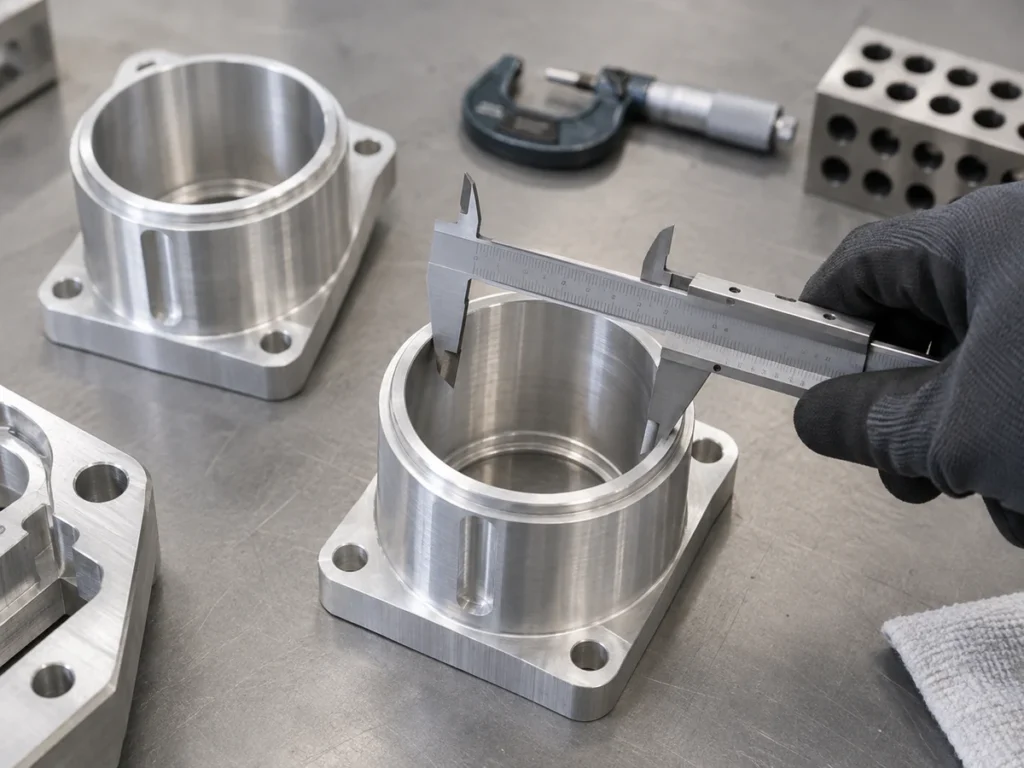
List the drawing’s required checks for the smaller hole and the surrounding seat separately. Keep the feature identity with each record.
Ask which measurement method and part condition the machining provider proposes. Retain the agreed evaluation basis where it is needed to interpret the result.
Keep machining and assembly records distinct
A dimensional record addresses the named geometry. If the order also requires an assembly review, retain its mating-part identity and acceptance basis.
A picture of a washer or screw on the part can help explain the arrangement. Ask for the required records before treating that picture as complete feature acceptance.
Identify the operations already completed on the inspected component. If finishing follows the seat machining, keep the agreed final acceptance stage in the delivery scope.
Make unresolved items easy to find
Put each open drawing question beside the affected feature. State who owns the clarification and retain the released answer with the order.
If a provider proposes a different seat, have the responsible design and manufacturing reviewers assess that change. Keep the original requirement visible until an approved revision replaces it.
The first-article inspection guide helps arrange the resulting evidence. Identify the actual part and checked revision in the sample decision.
Compare the complete delivered component
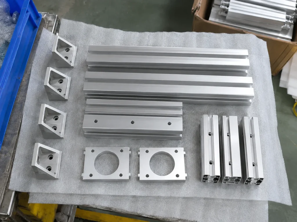
Check whether the price covers stock cutting, hole preparation, seat machining and required finishing. Name the actual included stages.
Ask for necessary records and packaging requirements to remain in the offer. Resolve missing work before comparing prices for the same delivered component.
For a cut-stock inquiry, send JiurunCut the aluminum section and cutting-stage drawing. Have the downstream machining provider confirm the required hole and seat work.
Keep spotface vs counterbore decisions connected to the assembly drawing. A saw-cut blank quotation alone does not define the complete seating feature.
Questions that settle the requirement
Can I choose by apparent depth alone?
Read the intended mounting function and complete released geometry.
Can a missing depth be copied from another part?
Ask the drawing owner to resolve the applicable requirement for this component.
Does the fictional 5 mm remainder approve the joint?
It is a geometric subtraction only. The example provides no accepted design or strength result.