
Start at the wheel deck and pedal mount: their brackets determine which T-slot faces must remain accessible after assembly. In sim racing cockpit aluminum profile cutting, a member can be exactly the called-out length yet arrive with its slot facing a bracket, an end that still needs tapping, or no label to distinguish similar uprights. Read the joint before programming the cut.
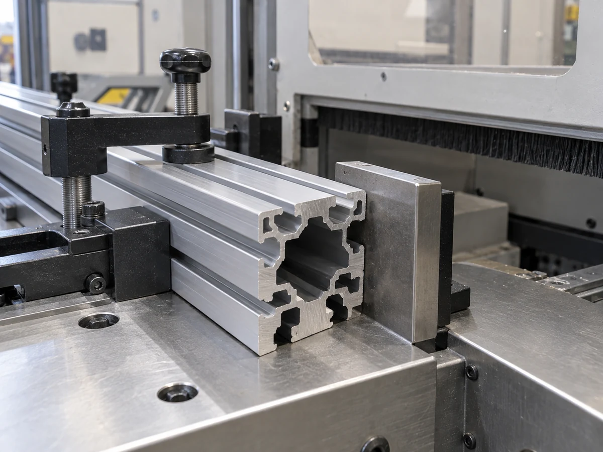
The three photos below are related views of T-slot sections, a generic frame member and a saw setup. They are illustrations only. They do not show the cited brands’ parts, a customer cockpit, an approved fixture, a trial cut or measured rig performance.
Locate the wheel, pedal and seat interfaces first
A complete cockpit contains more than a rectangle of extrusion. Sim-Lab’s GT1 Evo box contents list profiles alongside mounting hardware, wheel deck, pedal tray, side mount and feet. Trak Racer’s TR80 parts list also separates chassis and wheel-support profiles from pedal, seat and other fittings. These examples show why a pile of correctly cut rails is not automatically an assembly-ready kit.
Start a member map from the released cockpit design. For each rail, identify its assembly position, mating bracket or plate, visible faces, slot direction and required end condition. Include the hardware revision where the design requires it. Check wheel and pedal compatibility against the actual cockpit maker’s current information; the Sim-Lab product page treats that as a product-level question. A cutting supplier cannot infer it from an extrusion length.
Treat every slot as a connection face
Do not specify a replacement or custom frame member as “40-series profile, cut to length” alone. Release the exact end-view drawing, including outside envelope, slot opening, internal cavities, wall thickness and connector features. Mark which side of the section faces the wheel support, pedal support or base. Two profiles with similar outside sizes may have different connector and slot geometry. The responsible designer must approve any substitution.
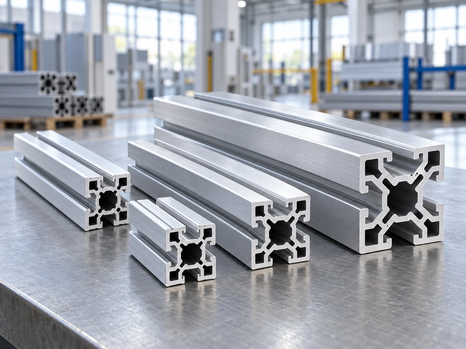
On the member map, give each piece a side or station name rather than relying on a nominal cut length. If a rail has different operations at its two ends, mark the datum end and the orientation before sawing. Identify holes, tapping, counterbores and brackets separately: a sawed face does not include those operations unless the work order explicitly assigns them.
Sim racing cockpit aluminum profile cutting: verify the first joint
The first-off inspection should confirm section identity, length from the released datum, end squareness or specified angle, burr limits and finish condition. Then the design owner should try a representative joint with the specified bracket and fasteners. A base rail and upright that meet their individual dimensions can still reveal a wrong slot orientation or missing secondary operation during that check.

When a joint fails, record what failed before shortening another member. If a bracket cannot engage, compare the released slot and hardware. If an upright sits at the wrong station, check its label and datum. If a connector needs a tapped end, verify that tapping was included in the assigned scope. The first-off record should say who accepted the cut blank and who accepted the assembled joint; those are different decisions.
Cut and pack in the order the frame will be built
For a repeated OEM build, group the released list by assembly station: base members, wheel-support members, pedal-support members and any side accessories where applicable. Use a part number, revision, quantity and orientation on each bundle. Keep left and right parts distinct even when their lengths coincide. This lets the assembler compare the physical set to the bill of materials without guessing from appearance.
Protect exposed faces and the slot edges that locate hardware. Agree on stock support and clamp-contact faces before the run, especially for long slender members. The cut-off also needs support as it separates. A representative setup can show whether the actual approved section stays located without new marks; a generic photo or video cannot certify a particular customer part.
Where the saw demonstration fits
This playable video comes from Jiurun Machinery’s own channel and shows a general aluminum-profile sawing workflow. It does not show a sim-racing cockpit, the cited makers’ components, an approved custom rig fixture, a customer trial or verified performance for this application.
If the goal is one damaged member in a named cockpit, get the maker’s replacement information or an approved matching drawing. For a released custom or OEM frame, send Jiurun the section drawing, member map, cut-end requirements and first-off limits. We can discuss an aluminum profile saw for the specified cutting work while the cockpit designer retains responsibility for the complete frame and hardware fit.