
The tool outlines have been approved, yet the printed panel will not slide into its new aluminum surround. A frame member may meet its stated length while the board opening, corner joint, or wall mounting still fails. For shadow board frame cutting, the useful starting point is the approved tool layout and panel construction, followed by a member-level cut list. The finished board and the saw-cut frame blanks are different purchasing stages.
A real product illustrates why these stages matter. LOTO Safety Products describes a shadow board with a PPC panel, an aluminum-alloy frame and separate nylon hooks. That description identifies different components; it does not tell a saw supplier the extrusion section, joint design or individual member length for a different board.
Choose the buying stage before specifying cuts
Ask whether the purchase is for a complete printed shadow board, a frame kit ready for assembly, or straight aluminum members only. If the board supplier owns graphics, hook positions, panel drilling and wall fixings, a cutting quotation should not silently include those tasks. Conversely, buying a complete board on the basis of a frame cut list leaves the tool layout and mounting decisions unresolved.
Record the panel material and thickness, whether it enters a continuous groove or sits behind the frame, the approved corner connector, the wall or stand mounting method, and the side from which the panel is installed. Request a sample of the actual profile and connector. A photograph of an outside dimension does not establish any of these interfaces.

Build a shadow board frame cutting schedule
Start with the approved drawing revision, not a nominal board size from a catalog. The visible tool field, physical panel size, frame outside size and extrusion cut lengths can all differ. The corner method determines how the members meet; a miter and a butt joint do not use the same length datum. Use the frame supplier’s approved joint drawing to derive each value. Do not apply a universal deduction from the outside size.
Give each member its own row: position on the board, profile part number and revision, alloy and finish if specified, quantity, length and measurement faces, end treatment, slot or groove orientation, and label. Mark which face must stay visible. If upper and lower rails have different grooves or fastener paths, identify them separately even when their nominal lengths match. State whether the saw delivers plain cut blanks or parts with a subsequent drilled or machined feature supplied by another operation.
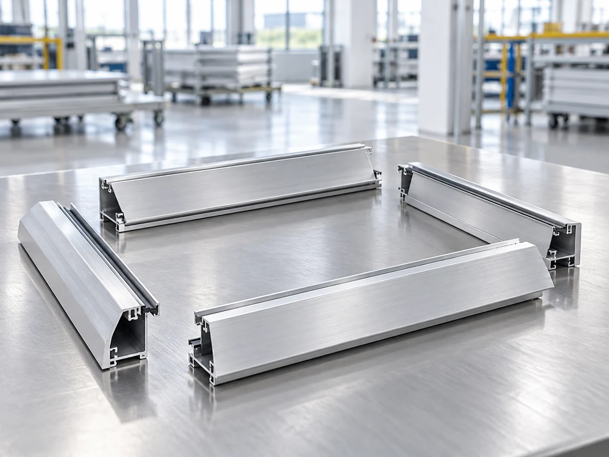
Keep the tool field usable after the frame is assembled
A frame that captures the panel can cover printed outlines, hook fixing points or a tool handle’s removal path. Confirm the clear field inside the assembled frame before releasing cuts. Place a full-size print or marked sample behind the proposed corner arrangement and check the outermost hooks, clips, labels and access to mounting holes. The panel designer owns the approved graphics and tool positions; the saw trial establishes only the cut-blank dimensions and end condition requested of it.
PAR Group’s custom shadow-board quotation inputs include size, tool shadows, clips, artwork and any pre-drilled holes. This is a useful reminder to resolve panel requirements with the board supplier before treating frame length as the whole specification. It is not evidence that PAR uses the aluminum frame shown here.
Approve one corner and one panel fit
Make a first-off set from the actual extrusion, finish condition and connector. Inspect cut length from the declared datum, both ends, the visible face, groove opening and damage at the corner. Then assemble one corner with a representative panel piece. Confirm that the panel enters and seats as intended and that any connector or screw remains accessible. If the profile is finished before cutting, agree what an acceptable exposed end looks like; if finishing follows cutting, record who owns the later finish and recheck.

The check must also cover the last member in the set. A successful single straight cut cannot prove that four members close around a real panel. Keep the approved first-off reference and the profile revision with the order, so a later repeat batch is compared with the same interfaces.
What to send in the RFQ
- The approved board layout revision, panel sample or panel drawing, and intended wall or stand mounting route.
- Actual aluminum extrusion section and finish, corner connector, and a member schedule with end types, datums and quantities.
- Which faces must stay free of clamp marks, the acceptable cut-end condition, and the first-off fit check.
- A clear boundary between saw-cut blanks, corner assembly, printed panel, hooks, drilling and installation.
If the board size or tool layout changes, return to the member schedule before ordering replacements. A panel revision can alter the required clear opening even when the outside frame size stays the same. For another example of why a corner system controls cut length, see our screen-frame corner-key guide; its dimensions and hardware must not be transferred to a shadow board.
The video below, from the Jiurun Machinery channel, shows an automatic straight-profile feeding and cutting scene. It is a general equipment illustration. It does not show a shadow board, the pictured frame profiles, a customer order, an approved joint, or measured performance for this job.
A practical release decision
For shadow board frame cutting, release the blanks when their identity, length datum, end treatment and first-off corner check meet the agreed drawing. Release the complete shadow board only after the panel, graphics, tools, hooks and mounting have their own acceptance. If you are comparing a saw for repeated aluminum frame members, send Jiurun the actual extrusion and approved cut list for a scoped trial; ask for the cut-result evidence you need, without assuming a particular machine model or output rate fits your job.