
A LiDAR mounting rail can be cut square, measured to the drawing, and still put a finished sensor in the wrong place. The saw produces an aluminum blank; the mounting design determines whether a bracket, adjacent member, or cable route enters the sensor’s field of view. Treat those as two separate approvals before you order a batch of cut rails.
This guide applies when an equipment builder has specified an aluminum extrusion or rail as part of a LiDAR support. It does not assume a particular sensor, Jiurun machine configuration, or proven sensing result. The sensor manufacturer and system integrator remain responsible for the installed device and its application.
Start with the sensor view, then define the aluminum blank
Ask for the sensor model, its approved mounting interface, the intended orientation, and the area it must observe. Mark the sensor’s optical opening and the required clear space in the assembly drawing. Only then locate the rail, brackets, guards, fasteners, and cable path around it. A rail that clears a two-dimensional end view may still cross the view when the sensor is tilted or the bracket is adjusted.
Blickfeld’s Qb2 mounting guidance calls for a stable base and an unobstructed field of view, and it describes final orientation adjustment while observing the point cloud. These are requirements for that device, not universal dimensions for every LiDAR. Use the selected sensor’s current documentation for the actual keep-clear envelope.
Release a cut drawing that the saw supplier can actually check
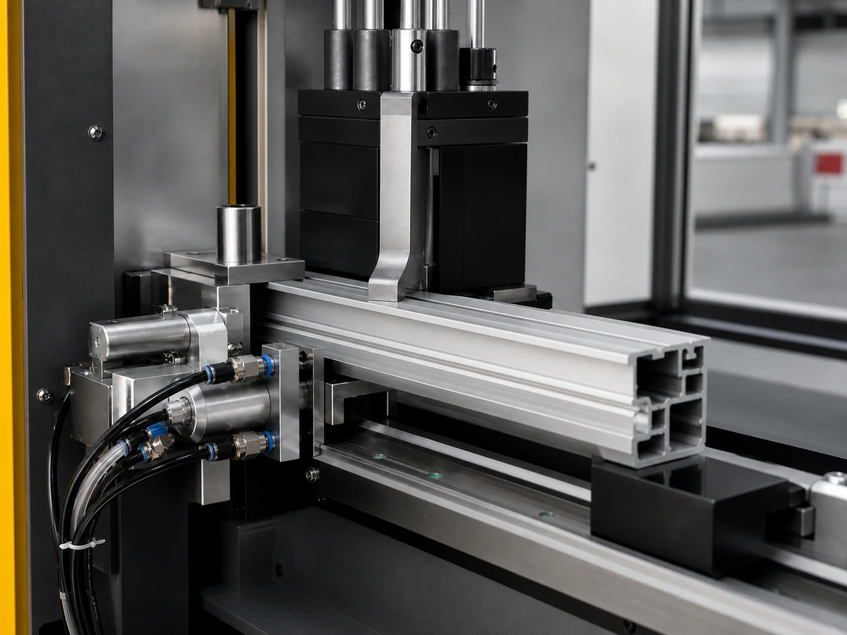
For the cutting operation, identify the exact extrusion cross-section and alloy, the finished blank length and tolerance, the end condition, the designated datum face, the quantity, and the allowed burr or edge condition. State whether holes, slots, or tapped features arrive in the stock, will be machined later, or belong to another supplier. Do not silently transfer a finished assembly dimension to the saw setup: a bracket offset and a rail length are different measurements.
If the stock is asymmetric, show which face is up at the saw and which end becomes the assembly reference. A simple end-view arrow can prevent the correct length being cut from the wrong orientation. On a trial piece, check the cut face against the specified datum and inspect both accessible and hidden edges for burrs. Record the measurement method and the number of pieces checked; a photo of a generic saw cannot establish the tolerance of your own blank.
Make the assembled LiDAR mount a second acceptance gate
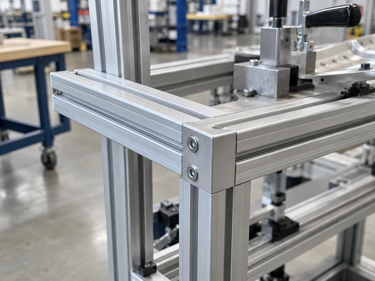
Once the LiDAR mounting rail blank passes its dimensional check, fit the actual bracket, sensor, fasteners, adjacent rails, and cables in their intended positions. Check the full adjustment range, including the worst permitted tilt and any nearby moving equipment. A cut end, fastening plate, or cable loop should not enter the manufacturer-defined view or interfere with the mounting interface. Check access for tightening and inspection without pushing the sensor out of alignment.
Support stiffness matters because the sensor’s orientation must remain where the integrator sets it. Blickfeld warns against shaking or vibration at its mounting location. Ouster’s Gemini Detect troubleshooting guide separately identifies near-sensor blockage and a changed sensor tilt as conditions to investigate at the mount. These examples show why dimensional acceptance at the saw is insufficient; they do not certify any particular rail or sensing performance.

Keep three sign-offs separate
- Saw blank: the cutting supplier confirms stock identity, length, datum orientation, end condition, and the agreed inspection record.
- Mechanical fit: the equipment builder confirms bracket interfaces, fastener access, routing, clearance, and stability with the specified sensor installed.
- Sensor operation: the sensor supplier or qualified integrator checks field of view, alignment, configuration, and application performance in the final environment. If the device is part of a safety function, follow the manufacturer’s instructions and the responsible safety validation process.
A pass at one gate is not a pass at the next. If a blank is too long, update the cut drawing and inspect another blank. If the blank is right but the bracket blocks the scan, revise the mounting arrangement rather than relaxing the cut tolerance. If the mechanical layout is clear but the installed point cloud is wrong, diagnose alignment and sensor setup with the integrator.
What to send with an aluminum rail cutting inquiry
Send a marked extrusion drawing, the blank schedule, the datum and orientation convention, acceptable cut-end condition, batch quantity, and the inspection plan. Include an assembly view that shows where the sensor and bracket sit, but identify the sensing requirements as the integrator’s separate responsibility. Ask for a sample blank before releasing the full batch when the profile or orientation is new.
For another example of separating a saw-cut member from downstream sensor hardware, see our conveyor sensor stand cutting checklist. It addresses a different support-kit inquiry; use the actual LiDAR drawing and device instructions for this project.
Equipment video: a related saw process
The following video from Jiurun Machinery’s own channel shows an aluminum cutting machine in operation. It is a related equipment demonstration only, not a LiDAR mounting-rail test, a sensor model demonstration, or proof of optical clearance.
Need a LiDAR mounting rail cut blank?
Share the specified aluminum profile drawing, cut schedule, and datum face with Jiurun to discuss the saw operation and a sample-cut check. Keep the LiDAR model, bracket layout, viewing envelope, and final sensing approval with your equipment builder and integrator. Contact Jiurun with the cutting requirements.