
A floorboard edge that will not seat in its side member offers a fit clue before anyone measures a replacement. In inflatable boat floor stringer cutting, a shorter member cannot fix the wrong groove or contact face. If the boards engage but an end conflicts with the manufacturer’s installation sequence, the cut datum deserves a separate check. Those faults call for different decisions at the saw.
The three photos in this guide are related profile, setup and end-inspection views. They do not show an identified boat stringer, a customer installation, an approved fixture, a trial cut or verified boat performance.
Read the floor installation sequence
On removable rigid floors, side stringers help hold the floorboard assembly in position. A Highfield owner manual shows numbered floor pieces fitted before aluminum stringers are installed along the sides. West Marine’s inflatable-boat guide also describes rigid removable floors and aluminum extrusions that retain their edges. These sources explain an assembly relationship; neither supplies a universal section or cut length for another boat.
For a repair, identify the maker, model, floor type and current parts revision. Photograph where the original side member sits with the floor assembled, then compare the maker’s specified replacement and instructions. West Marine’s separate model-specific replacement floorboards illustrate why the boat and floor system matter. They do not prove that an arbitrary aluminum angle will replace a missing stringer.
Trace the panel edge through the section
An end-view drawing should show the lip, groove or other face that receives the floorboard edge, the surface facing the boat side, and any exposed finish face. Name the port and starboard member separately if the released design does. Include the exact extrusion designation, material and finish only when those are documented by the design owner. An outside width or photograph of a worn rail cannot establish connector or contact geometry.

Before batch cutting, the responsible boat maker or assembler must confirm that the released section meets the actual floorboard and adjacent components. If a board edge will not enter, inspect the profile and board interface first. If a member fits only when reversed, check the side label and orientation. Do not remove material from a contact lip simply to make a mismatched part appear to fit.
Set the cut datum after the contact face is known
The saw drawing needs a measured length datum, required end angle or squareness, and any allowance for later fitting. Mark which end is the datum and whether the opposite end receives relief, radius or other work. Holes, slots and hardware interfaces are separate operations unless explicitly assigned to the cutting supplier. A straight cut by itself does not recreate them.
For a long or thin-walled extrusion, specify infeed and cut-off support, stock length, clamp-contact faces and surfaces that must remain unmarked. The face that registers against the stop should be the one chosen by the released drawing, not an edge selected because it looks convenient in a photo. A stopped setup with the actual approved section can reveal movement or visible marking before production begins.

Diagnose a first-off at the bench and at the floor
At the saw bench, record the first blank’s section identity, length from the stated datum, cut-face angle, burr condition and finish damage against drawing limits. At the floor assembly, the design owner checks whether the approved part engages the panel edge in the documented order. Keeping those two records separate makes a failed first-off actionable.
- Wrong engagement: compare the released groove or lip to the floorboard edge and check whether the member is reversed. A shorter saw length does not solve a cross-section mismatch.
- End interference: compare the part’s datum and any fitting allowance with the maker’s installation sequence before changing the stop position.
- Visible burr or mark at a contact face: identify whether the cut, clamp or handling caused it and use the specified acceptance limit. Do not silently relax the floor-fit requirement.
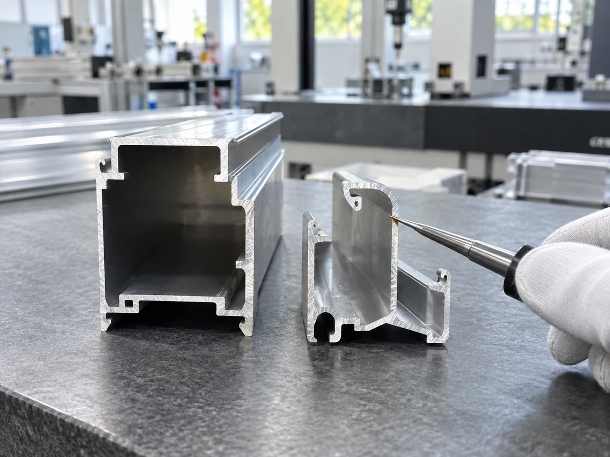
A passing blank inspection establishes only the documented cutting conditions. It does not approve a substituted section, completed floor system or on-water performance. If a sample fails, record the deviation and adjust one controlled cause such as support, stop reference, cut allowance or handling, then repeat the specified check.
Keep the pair and its evidence together
Ship port and starboard pieces with part numbers, revisions, quantity, orientation and cut status. Protect ends and exposed faces from rubbing. Keep the accepted first-off record with the production lot and rejected pieces apart from approved members. If a damaged floorboard or joiner is the real issue, resolve that with the boat maker before ordering more aluminum blanks.
What the equipment video can show
The playable video below is from Jiurun Machinery’s own channel. It shows a general aluminum-profile cutting workflow. It does not show an inflatable-boat stringer, a named boat model, an approved fixture, a customer test or verified performance for this use.
For a known repair, obtain the maker-approved replacement and assembly instructions. For repeated cutting of a released extrusion, send Jiurun the section drawing, floorboard-edge interface, side-specific list and first-off limits. That lets a machine discussion address the cut while the boat maker or responsible assembler owns the fit of the complete floor.