
Gear module vs diametral pitch compares two descriptions of gear tooth size. Module uses pitch diameter in millimeters divided by tooth count. Diametral pitch uses tooth count divided by pitch diameter in inches. Their numbers run in opposite directions as tooth size changes.
When reviewing a transmission spare for an aluminum-production machine, preserve the actual gear identity and approved drawing. A tooth-size conversion is one check within that review; it does not approve a replacement gear or establish the machine’s fitted transmission.
Start with three checks
- Identify the tooth-size system and its units.
- Keep pitch diameter separate from outside diameter.
- Retain the complete selected gear and mating-system definition.
On this page
1. Read gear module vs diametral pitch with units
KHK’s gear-module explanation defines module m as pitch-circle diameter d divided by number of teeth z, with d in millimeters. Its diametral-pitch explanation defines DP as z divided by d measured in inches.
A larger module describes larger teeth. A larger DP describes smaller teeth. Do not compare the bare numbers as though both increase with tooth size.
| System | Definition |
|---|---|
| Module m | Pitch diameter in mm divided by tooth count. |
| Diametral pitch DP | Tooth count divided by pitch diameter in inches. |
Write the system beside the numerical value in a spare-part record. A note containing only “pitch 12” leaves the intended quantity unclear. Ask the issuer to supply the complete definition from the approved gear reference.
Keep tooth count independent. It describes how many teeth the gear has. It is not itself a module or a diametral-pitch value.
2. Keep pitch diameter separate from outside size
KHK’s standard spur-gear calculation section separates reference diameter from tip diameter. For its standard non-profile-shifted external spur-gear case, reference diameter is z multiplied by m, while tip diameter adds two modules to that diameter.
Use that specified case for the following original example. Assume a fictional standard external spur gear has 32 teeth and module 1.5. Its reference diameter is 32 × 1.5 = 48 mm. The corresponding standard tip diameter is 48 + 2 × 1.5 = 51 mm.
Dividing the 51 mm tip diameter by 32 teeth gives 1.59375, not the specified module 1.5. The wrong diameter produces the wrong interpretation even though the arithmetic itself is correct.
The example is a definition exercise, not an actual gear design or measured spare. Its standard tooth-form assumptions must remain visible. Do not apply its tip-diameter shortcut to a different gear type or an unspecified modified tooth form.
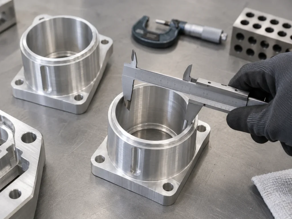
For a real replacement, identify the drawing’s named diameter. A caliper’s outside reading does not become a pitch-circle measurement just because it is the easiest dimension to obtain.
This is a common gear module vs diametral pitch mix-up: changing the length unit cannot correct using the wrong diameter in the first place.
Convert tooth size without approving a substitute
KHK gives the relationship m = 25.4 / DP. For a fictional 12 DP gear, that produces module 2.116666… . Rounding it to module 2 changes the stated tooth size.
Assume that 12 DP gear has 24 teeth. Its pitch diameter is 24 / 12 = 2 inches, or 50.8 mm. A separate module 2 gear with 24 teeth has a 48 mm reference diameter. These are different stated geometries, despite the nearby module numbers.
Keep the converted value and the original designation together. Show the number of digits used for communication without treating a rounded preferred value as the original specification.
A gear module vs diametral pitch conversion answers a unit question. Retain the mating gear definition and obtain an approved selection before treating two catalog items as substitutes.
3. Retain the tooth system and full component identity
KHK’s module guide also distinguishes normal and transverse module for helical tooth systems. It warns that a shared numerical module and helix angle do not make different referenced tooth-profile types mesh correctly. Preserve the stated reference system.
For the actual gear, record the manufacturer or controlled drawing identity, revision and gear type. Keep the specified tooth-size designation, tooth count and any pressure-angle or helix requirements with that record.
Identify the bore, hub, face width and mounting features from the approved component definition. Have the responsible supplier review the complete assembly relationship. The tooth-size field does not define those mounting features.
Retain material, treatment, accuracy and load requirements where the actual design specifies them. This article supplies no universal load rating, backlash, service life or installation setting for a proposed spare.
If the spare is part of a complete supplier assembly, preserve that assembly reference. Replacing an internal component can require more information than ordering another item with a matching outside envelope.
Keep the machine or assembly owner involved in substitutions. A calculation can reveal a mismatch without identifying the correct replacement by itself.
Prepare the transmission spare-part handoff
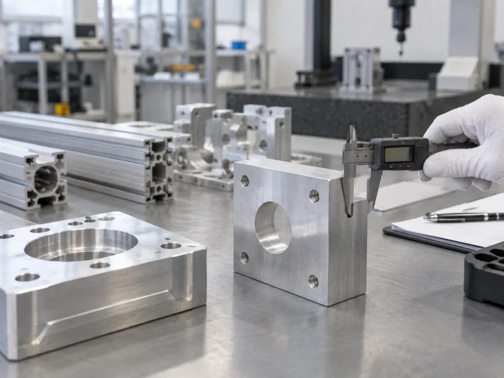
Send the machine or assembly identity, the existing controlled spare reference and the required delivery stage. Add the approved drawing and clear photographs that identify the actual component where available.
Separate a loose gear from a shaft-mounted gear, a matched gear set and a complete transmission assembly. Identify which mating and mounting components the quotation includes.
When comparing gear module vs diametral pitch in supplier replies, check that both replies describe the same reference system and approved assembly. Record unresolved fields explicitly rather than completing them from an outside measurement.
A leadscrew uses different pitch and lead definitions. Our thread pitch and lead guide explains that separate axial-motion question. Do not carry a thread-pitch designation into a gear-tooth record.
For a coupling in the same transmission, retain its own complete identity. The flexible-coupling guide covers that separate connecting component. Its dimensions do not establish the gear’s tooth system.
Quick answers about gear module vs diametral pitch
Does a higher DP mean larger teeth?
No. DP increases as the stated tooth size becomes smaller.
Can I divide the outside diameter by tooth count to obtain module?
The module definition uses pitch diameter. Keep that reference distinct from the outside measurement.
Does a converted module approve a replacement gear?
No. Retain the full gear, mating assembly and approved selection.
Define the aluminum cutting requirement separately
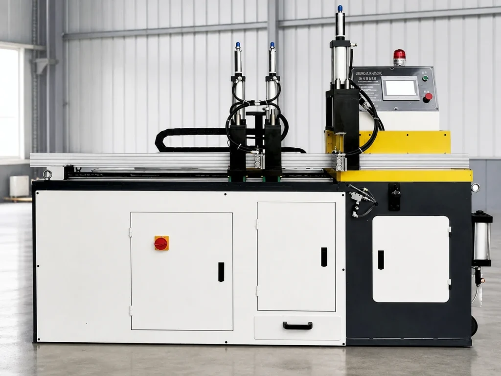
Send JiurunCut the aluminum section, required cut dimensions and quantities for a cutting review. If a transmission spare is also involved, include its controlled assembly reference and the gear module vs diametral pitch question for the responsible supplier to resolve.