
Extruded aluminum enclosures can combine a cut body, internal mounting features, end panels and separate hardware. A cutting order needs to identify the body as its own component. The length of that blank is not automatically the overall assembled case length or the space available for a circuit board.
Four questions clarify the work: which body is being cut, which length controls the blank, which interfaces need checking, and what stage is delivered? Answer them before comparing a cut-stock quote with a finished-enclosure quote. The two offers may cover different work even when their photographs look similar.
Start with the component drawing
- Identify the exact body section and cut-length reference.
- Keep internal space, end-panel fit and overall size separate.
- State whether the supplier delivers blanks, processed bodies or complete kits.
On this page
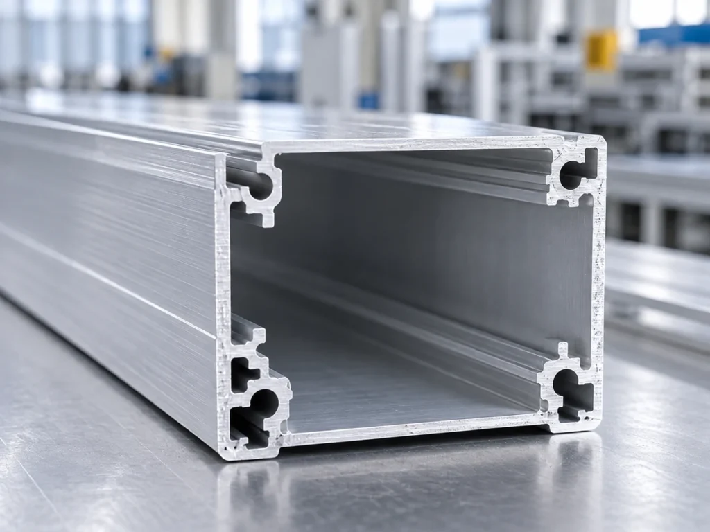
Extruded aluminum enclosures: which body is being cut?
Identify the body part number, section drawing and revision. Show the cross-section with its important internal and external features. A description such as “small aluminum box” is too broad to define a cutting job.
Hammond’s 1455 series gives a real example of extruded bodies with internal board slots and versions that include a removable sliding plate. Its metal and plastic end-panel versions differ. These are product-specific details, not features to assume for every custom housing.
Another construction appears in Hammond’s 1455ZT series: a U-shaped extrusion works with a sliding bottom plate and end mounting brackets. The example shows why the buyer must identify the full construction rather than order solely from an outside silhouette.
For your own order, list each supplied component separately. If the drawing shows two body halves or a sliding plate, give them separate identities. Ask the supplier to quote the components actually within its scope.
Which length controls the blank?
Mark the cut length on the body drawing. Define the faces used to measure it and the applicable tolerance. Keep that requirement separate from the assembled enclosure envelope, which belongs on the assembly drawing.
A supplier table may use length or depth for a product’s main dimension. Read the table heading and associated drawing before transferring the value to a cut list. Use your controlled feature reference to remove doubt about what is being measured.
TAKACHI’s MX product table lists external and internal dimensions separately, and its product description identifies an extruded aluminum frame with plastic panels and internal board grooves. The practical lesson is to check both spaces in the relevant product drawing; an outside size alone does not describe board clearance.
When a custom body length changes, ask the assembly owner to confirm the updated end-panel and internal-space requirements. Do not extend a catalog statement from one enclosure into a new custom design without that review.
Which interfaces need separate checks?
Identify the interfaces that matter to your assembly: board grooves, sliding covers, end panels, mounting brackets or other defined features. Point each requirement to the relevant component drawing. Keep dimensions and feature identities together.
For the body-to-end-panel joint, agree the checks needed on the cut faces and the mating components. Ask the design owner to specify the accepted condition. A visually neat cut should not be used as evidence that an end panel, connector opening or fastener pattern has been approved.
For a board-mounted design, identify the board envelope and its intended support features in the assembly review. The purchasing team should gather the approved fit requirements rather than choose a groove size from a generic image.
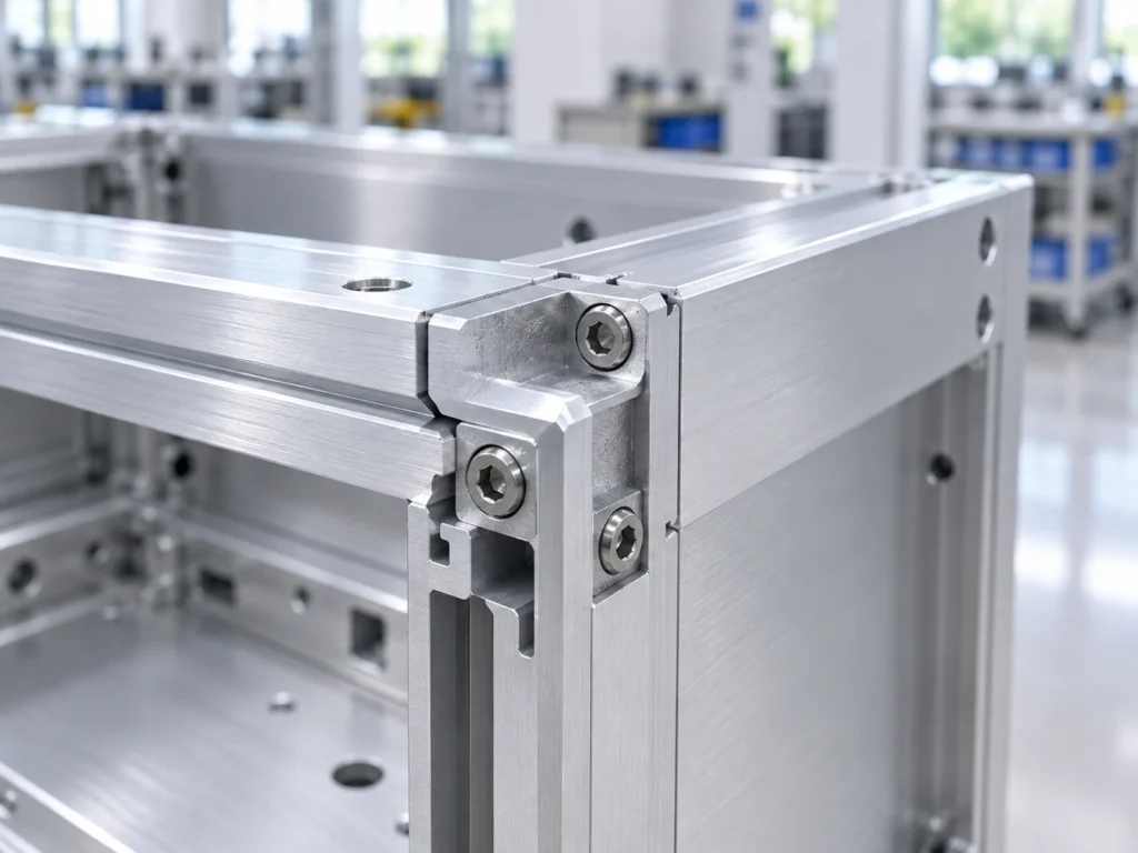
Keep drilling and connector cutouts visible as separate operations. Our cutting and drilling guide explains how to assign those stages. Do not assume that a saw-cutting quotation includes later machining because the completed sample shown in a photograph has holes.
What stage does the supplier deliver?
Choose a clear scope description: cut body blanks, machined bodies, finished bodies or complete enclosure kits. List the included and pending operations. The buyer should be able to see which team owns each unfinished requirement.
For a cut blank, define the incoming stock condition, supplied length, cut-face requirements and identity labels. For a processed body, add the applicable machining and finish documents. For a kit, also identify the required panels and hardware.
Keep the finishing sequence linked to the supplied stage. If dimensional allowances around anodizing matter, have the designer and finisher resolve them in the controlled requirements. See our anodizing thickness and fit guide for the separate coating and final-dimension fields.
Assign any required enclosure performance review to the responsible assembly owner. This purchasing guide does not establish ingress protection, electrical bonding, thermal performance or electromagnetic shielding for a cut body. Request the applicable assembly evidence when those requirements are part of the project.
A fictional body-versus-assembly example
Consider fictional housing H14, revision C. Its assembly drawing defines a 180 mm body and an end-panel arrangement that adds 4 mm beyond each body end. These invented dimensions illustrate document bookkeeping; they do not describe a catalog product or a recommended enclosure design.
| Fictional drawing item | Value and meaning |
|---|---|
| Body blank length | 180 mm between the defined body end faces. |
| Defined added length | 4 mm at each end in this particular fictional assembly. |
| Assembly total | 180 + 4 + 4 = 188 mm. |
| Internal board space | Requires its own drawing and fit check; not established by either total. |
If the cutting order mistakenly asks for a 188 mm body, it has copied the assembly total into the blank field. Correct the requirement before release. Do not ask the cutting supplier to guess which dimension the buyer intended.
The example does not mean that all end panels add their thickness to the body length. Their actual arrangement controls the relationship. Refer to the approved assembly drawing instead of applying the invented calculation to a different housing.
Keep body and kit quantities clear
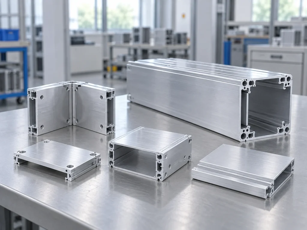
Count the ordered body blanks separately from complete kits. If a kit needs one body and two panels, the packing record should show those component identities and quantities. State whether hardware is included, separately supplied or outside the order.
Keep different body lengths and revisions separated in the labels. Show any held components clearly, so they are not mixed into the released kit count. A crate containing the right total number of parts may still have the wrong combination.
For example, 20 bodies and 38 panels could form at most 19 two-panel kits by count alone. That arithmetic does not confirm compatibility, condition or release. The accepted kit quantity still depends on the agreed component and assembly checks.
Prepare a cutting review
Send the body section drawing, controlled length dimensions, material condition, quantity and supplied-stage requirements. Include the relevant interface references and identify the next operation. State which questions remain with the designer, finisher or assembly supplier.
Use the cutting RFQ checklist to organize the information, then send it through JiurunCut’s contact page. Ask the proposed supplier to confirm what its cutting review covers for your actual profile.
A useful response addresses the body, support and handling requirements alongside the part drawing. Keep any sample-review findings tied to the exact material and revision. A different section or altered interface should receive its own review.
Buyer questions
Can I order the body using the assembly’s outside length?
Use the body component dimension. The assembly drawing must define how panels and other components relate to it; the two lengths should not be silently substituted.
Does a cut body mean a complete electronics enclosure?
No. Check the supplied scope and bill of materials. Panels, hardware, machining, finishing and assembly approval need clear owners where they are required.
Can the internal board size be inferred from an outside dimension?
Use the approved internal-space and interface drawing. An outside dimension by itself does not provide the required fit evidence.
Do these pictures show qualified enclosures?
No. They are editorial illustrations of housing and interface concepts. They do not document a tested assembly or a specific supplier’s catalog product.