
Chamfer size needs a defined measurement direction. A distance along an adjacent face and the width across the sloping bevel describe different lines. Before quoting or inspecting an aluminum part, identify which line the drawing actually dimensions.
A familiar number can hide that difference. For a simple right-angle corner, two equal face setbacks of 1 mm produce a sloping cross-section length of about 1.414 mm. Specifying a 1 mm sloping length would produce a different shape.
The three errors to catch
- Calling every visible dimension the bevel width.
- Reading an angle without its reference face.
- Checking an unspecified edge or a different part revision.
On this page
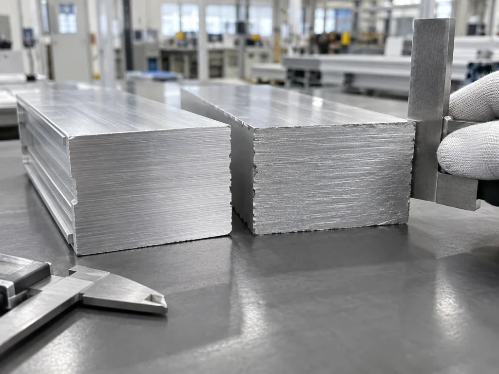
1. Identify what the chamfer size dimensions
Read the drawing’s dimension lines and section view together. Establish the original intersection of the adjacent faces, the points where the bevel meets those faces, and the exact distance the callout controls.
A setback follows an adjacent face away from that original intersection. A sloping cross-section length connects the two bevel endpoints in the defined section. Label these lines separately when clarifying an ambiguous drawing.
Onshape’s primary chamfer documentation illustrates several geometry definitions: equal distances, two different distances, or a distance paired with an angle. Its distance-and-angle example also identifies the face from which each is measured. These are useful distinctions when reviewing geometry; the software example does not interpret an unidentified drawing symbol for you.
Ask the drawing owner to resolve an unclear callout using the controlled drawing and its applicable conventions. Do not infer a complete requirement from an unlabelled CAD input, a photograph or a familiar shorthand alone.
Retain the units with the value. If a supplier translates the requirement into another representation, request a marked view that shows how the translated dimensions refer to the same edge.
Keep the corner-radius requirement separate. A curved edge and a straight bevel do not become interchangeable because their written dimension happens to use the same number.
Two invented 1 mm dimensions produce different corners
Consider an idealized two-dimensional section through a corner where two planar faces meet at a right angle. A straight bevel joins one point on each face. For this example only, the two setbacks from the original corner are equal.
Call each setback a, and call the straight line joining the bevel endpoints b. The example is a right triangle, so b² = a² + a². Thus b = a × √2, and a = b ÷ √2.
If both setbacks are 1 mm, the bevel line in this section is about 1.414 mm long. If that bevel line is 1 mm long instead, each equal setback is about 0.707 mm.
| Defined input | Other section dimension |
|---|---|
| Equal setbacks a = 1 mm | Bevel line b ≈ 1.414 mm |
| Bevel line b = 1 mm | Equal setbacks a ≈ 0.707 mm |
The arithmetic explains why the measurement line matters. It does not select a suitable edge for your component or establish a manufacturing tolerance.
These values describe the invented planar section only. They are not a measurement of any photograph, a universal conversion for every corner, or a description of a cylindrical or curved-face chamfer.
For an actual part, preserve its specified geometry and reference system. If the geometry differs from the example, ask the responsible drawing owner to define the required relationship rather than applying this simple triangle automatically.
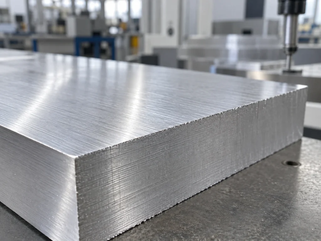
2. Keep the angle attached to its reference face
An angle needs two identified directions or surfaces. Locate the face or line used as the reference, then keep that reference beside the value in the quotation and inspection plan.
For the ideal right-angle section above, equal setbacks make the bevel line 45 degrees to each adjacent face. That result follows from the example’s geometry. It does not authorize treating every unspecified chamfer as 45 degrees.
When a drawing specifies unequal distances or a distance with an angle, read the orientation carefully. Identify which distance belongs to which face and where the angle begins.
If a supplier sends a revised model, compare the labelled definition with the approved drawing. A model can look broadly similar while placing the distance or angle on a different side of the corner.
Use an enlarged section or detail view to resolve that difference. Ask the supplier to reference the affected feature and drawing revision so the clarification becomes usable by the next person.
Do not approve a feature from an image whose perspective hides one face. Keep the dimensioned evidence with the drawing instead of relying on visual resemblance.
3. Define which edges the requirement covers
Identify each controlled edge by a view, feature label or other agreed drawing reference. Distinguish a specified bevel on one end from a general treatment of remaining edges.
For a saw-cut aluminum member, state whether the dimension applies to the end perimeter, a selected corner, a hole edge or another downstream feature. Keep the part’s orientation visible when opposite ends have different requirements.
Our post-cut deburring guide addresses the edge-treatment handover more broadly. The present check concerns the exact dimensioned geometry that a particular feature must have.
Keep the delivered stage explicit. A quoted cut blank may precede a separately specified machining or finishing operation. Assign responsibility for that operation before treating the member as a completed part.
If coating or another later operation affects the inspection stage, record when the specified check is required. Ask the design and quality teams to resolve that stage in the approved plan.
Preserve the limits given by the controlled documents. This article supplies no preferred chamfer tolerance, tool choice, cutting setting or instruction to rework an uncertain edge.

Turn the clarification into a usable inspection record
Create one entry for each distinct requirement. Include the part reference, drawing revision, affected edge, dimension definition, units, specified limits and required delivery stage.
Ask the inspection team to state the method and reference used for that defined feature. Keep an individual reading connected to the line or angle it actually measures.
If a report says only “chamfer: 1.02 mm,” the buyer still needs to know what was measured. Was it a face setback, the sloping line in a section, or another explicitly defined quantity?
Resolve that meaning before comparing the result with the drawing. A numerically close value for a different quantity does not answer the specified check.
Keep approved clarifications with the order and inspection records. If the drawing changes, review the affected feature entries and separate the previous requirement from the new one.
Quick questions before accepting a quote
Can “1 mm chamfer” always be read as a 1 mm sloping width?
Identify the dimension line and governing drawing convention. The simple example shows why an adjacent-face setback can describe a different quantity.
Can an angle be checked without a reference?
Keep the relevant face or line identified so the reported value answers the same requirement.
Does a photograph establish the finished feature?
Use the controlled drawing and agreed inspection evidence. The illustrations here show context, with no measured acceptance result.
Keep edge requirements visible in your aluminum inquiry
Send JiurunCut the section drawing, finished lengths and downstream edge requirements. Identify the chamfer size and delivery stage so the cutting proposal can address the actual member handover.