
A ceiling baffle can be cut to the scheduled length and still arrive with the wrong end. One run may need a flush plug at a visible perimeter; another may use a splice to continue the line. A maintenance bay may have to come down independently. These are different end conditions, and the saw cannot decide among them. For ceiling baffle ends, release the cut list only after the ceiling system designer has identified what each end must do.
This guide addresses the handoff between the approved ceiling detail and cutting an eligible aluminum blank. It does not certify a ceiling system or make a generic saw trial evidence of installed appearance, access, fire protection, or structural performance. The system manufacturer and installer retain those decisions.
First confirm what is actually being cut
“Metal baffle” does not identify a single saw input. Gordon’s Fin Mate linear ceiling product information, for example, lists both extruded aluminum and breakformed metal options. A buyer should therefore obtain the exact approved product and stock form before asking a cutting-machine supplier to quote a process. A length of extruded aluminum profile may be a practical sample for a circular-saw assessment; a formed or finished system component may call for a different manufacturing route and different responsibility.
Ask whether the purchase is for loose extrusion blanks, factory-finished baffles, or a complete ceiling kit. Identify which party supplies the plug, splice, clip, finish, and installation drawing. If the project calls for a proprietary baffle system, use its current approved detail rather than copying dimensions or attachment rules from another manufacturer. The cutting specification begins at that boundary.
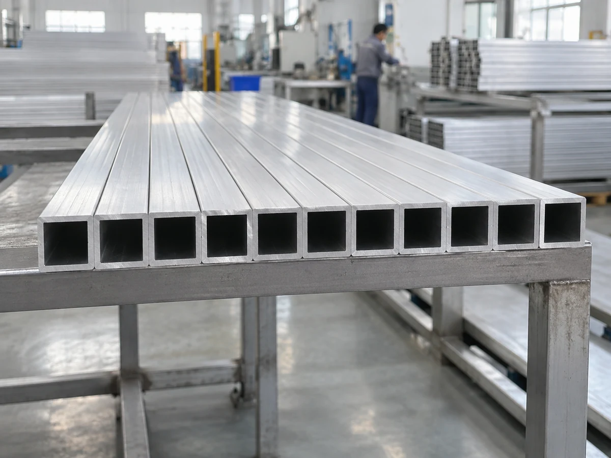
Mark the purpose of both ends on every piece
A plan dimension by itself may not show which end remains exposed, meets a wall, receives an end plug, or joins the next length. Put a left/right or datum-end convention on the cut schedule and tie it to the reflected ceiling plan. If the finish is directional or one face is visible from the occupied space, mark that too. This avoids treating two equal-length pieces as interchangeable when their installed roles differ.
The USG Paraline Baffles installation guide is a useful example of why the distinction matters: it documents end plugs and splices as separate system components and shows where they are installed. Those details apply to that USG system. They are evidence that termination choices exist, not a universal specification for other baffles or a Jiurun machine test.
| End condition on the approved drawing | Question to settle before cutting | What the sample must demonstrate |
|---|---|---|
| Exposed end with plug or cap | Which supplied component and visible-face orientation apply? | The actual component seats as specified, with an acceptable finished edge. |
| Continuous run with splice | Where is the joint and which two pieces meet there? | The actual splice can be assembled without damage or unwanted gap. |
| Independent access area | Must this piece be removable without moving its neighbor? | The approved connection and access method work in a representative assembly. |
| Wall or other termination | Is an exposed end, reveal, end cap, or manufacturer-defined clearance required? | The end detail matches the approved drawing, not an assumed nominal length. |
This table is a decision aid, not a substitute for the ceiling supplier’s installation instructions. Do not add an allowance merely because a different system uses a similar-looking baffle.
Inspect ceiling baffle ends with the real plug
If a plug is part of the approved design, obtain a physical sample from the same system and revision as the baffle stock. Compare the cut opening, internal ribs or returns, and the direction in which the plug is installed. A burr, collapsed wall, chipped coating, or distorted lip can prevent the plug from seating even when the tape-measured length is correct. Equally, a neat free end does not prove plug retention or finish acceptance.
Define the inspection point carefully. The cutting supplier can show an as-cut end and, when the part and accessory are supplied, a trial insertion. The ceiling-system owner should approve appearance, retention, and assembly criteria. If plugs are fitted after coating or other downstream work, specify which stage the sample represents. Keep as-cut dimensions, post-finish appearance, and installed acceptance as separate records; one photograph cannot stand in for all three.
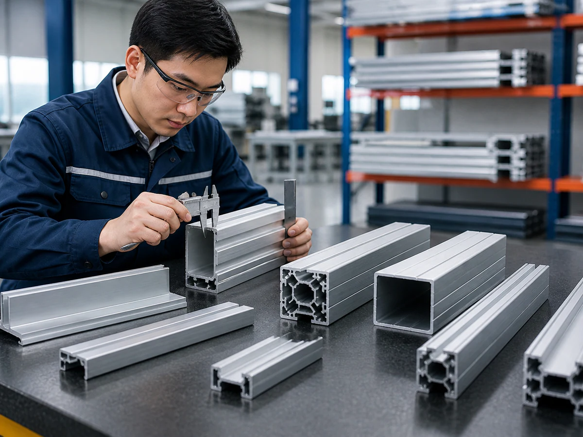
A splice can change the access plan
The cut schedule should not quietly convert an independently removable bay into a continuous run. In its Paraline guide, USG states that baffles connected by splices are not independently accessible and describes unspliced or capped ends for independent access areas. That is a specific manufacturer’s installation rule. It illustrates the kind of question the ceiling designer must settle before releasing cuts; it does not establish a rule for every ceiling system.
Mark service zones, joint positions, and intended removable pieces on the approved layout. If a splice is chosen, identify the actual accessory and the assembly sequence. If independent access is required, have the system supplier confirm the end treatment and support arrangement. The saw operator should then receive the resulting piece list and visible-face orientation. Cutting first and deciding access later can leave the wrong joint in a finished run.
For a representative trial, place the two cut pieces and the supplied joining part in the intended order. Check whether the connection can be made without forcing a distorted profile, whether the seam falls at the specified location, and whether any exposed finish damage is visible. This is an assembly check for the supplied sample, not proof that a completed ceiling meets building or maintenance requirements.
Turn the approved end detail into a cutting trial
Once the system owner has identified an eligible extrusion blank, send the cutting-machine supplier an actual section or a reliable cross-section drawing, stock length, alloy and temper when known, finish stage, required cut lengths, quantity mix, datum, visible face, and cut-end acceptance criteria. Include the real plug or splice if their fit is part of the trial. State whether the baffle can be supported on a flat face or needs a shaped support that avoids marking or crushing the visible surface.
The trial should begin with the actual stock rather than a convenient generic tube. Record the incoming section condition, blade and clamping setup, cut orientation, measured length method, end-face condition, and whether the supplied accessory can be assembled. If the profile bows, twists, or varies from lot to lot, record that separately from saw-induced error. A single acceptable cut is an initial sample; a production decision also needs the specified length mix and a repeatable inspection plan. Do not borrow a machine’s catalog positioning figure as a guarantee for the finished ceiling part.
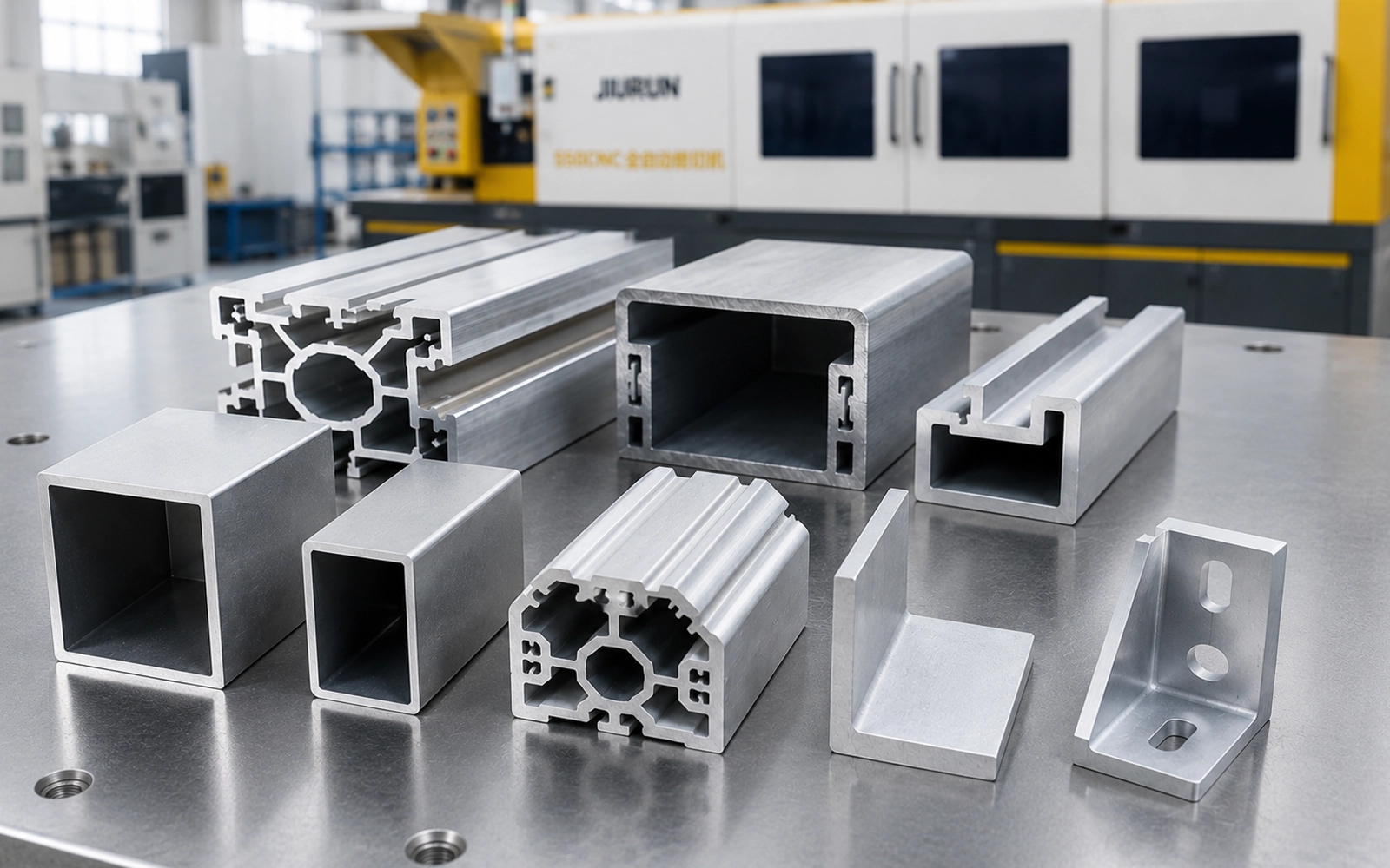
The short video below shows a Jiurun semi-automatic aluminum cutting machine and its general operating context. It is included to help discuss feed and support around a saw. It does not show this baffle system, a plug or splice trial, the quoted machine configuration, or finished-part performance.
What to send with the inquiry
Send the ceiling-system maker’s approved profile and end-detail drawing, a labeled cut schedule showing each piece’s two end roles, the plug or splice part numbers or samples, finish and visible-face rules, access zones, required quantities and lengths, stock form, and the stage at which inspection occurs. State who approves system assembly and who accepts the cut blank. If the input is breakformed or already finished, say so before discussing circular-saw equipment.
Jiurun can review the saw-cutting portion against the actual aluminum section and requested sample criteria. For the broader question of whether a baffle product is a suitable saw input, see our ceiling profile cutting overview. To discuss a specific eligible blank, contact Jiurun with the drawing, sample and end-condition schedule. We can then separate the cut trial from the ceiling supplier’s plug, splice, access and installation approvals.