
A small step at a light-frame corner can be conspicuous above a billiard table. The individual members may all meet their length callouts, yet the assembled rectangle looks uneven, a diffuser catches at a joint, or a clamp mark lands on the face everyone sees. For billiard light aluminum frame cutting, the useful question is where the installed frame reveals an error and which earlier operation caused it.
The housing route must come from the fixture designer. LiTE Systems describes its FiN frame as CNC-machined aluminum; Perimeter Billiard Lights describes a segmented aluminum-housed light. They are different products. Neither page identifies the section, saw process or acceptance limits for another OEM’s light. The checks below apply when an OEM has already approved an aluminum member drawing and is evaluating its cutting step.
Begin with the line visible from the table
A frame drawing should identify the face that remains exposed after installation. It should also show which surface seats against the corner connector, where the diffuser or optical insert enters, and where suspension hardware meets the housing. Those references may be on different sides of the profile. If a shop measures one face while assembly locates from another, identical cut lengths can still produce a visible step.
Make a simple member map: two long sides, two ends and any intermediate pieces the released design actually uses. Give each member its own orientation arrow, end form and drawing revision. Do not infer the number of segments from a photograph or copy another supplier’s bill of materials. A mitered corner, a square end under a cap, and a connector hidden inside a hollow section put different demands on the cut face.
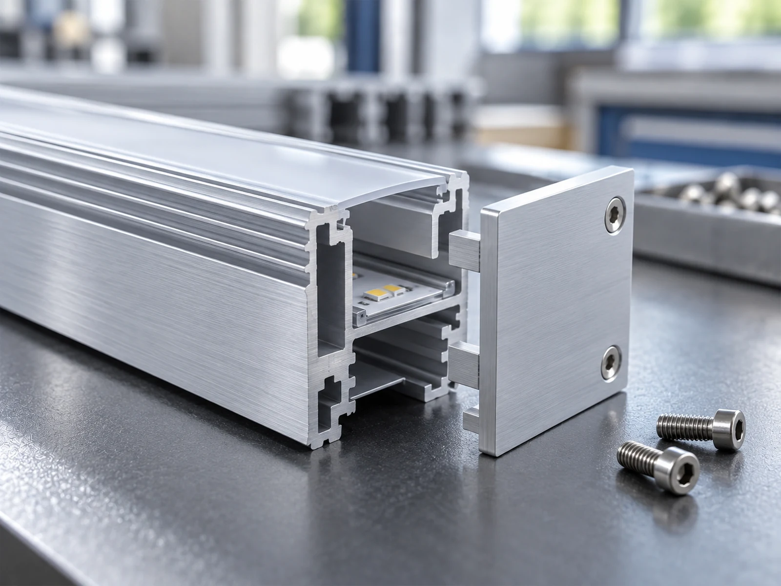
Trace a bad corner before changing the saw setting
When a first assembly looks wrong, separate the symptom from the cause. Measure the approved section and the mating part before blaming the length stop. A straight cut cannot correct a groove that is in the wrong place or a corner insert that does not match the released profile.
A proud edge at one corner
Compare section orientation and connector seating on both members. Then ask whether the same face was used for clamping, measurement and the assembled reference.
A diffuser that catches at the joint
Look at the groove, burr and any cap or connector intrusion. If a lip blocks insertion, identify whether it came from the cut, deburring or the mating part.
A rectangle that closes on one end and opens on the other
Measure both diagonals and check end forms with the intended corner parts. The cut question is whether angle, long-point dimension and member pairing stayed consistent.
One assembled side appears short
Confirm whether the drawing calls for an inside, outside or long-point length. Check that the stop setting and inspection used the same datum.
This is a diagnostic sequence, not a claim that any pictured profile has these faults. Record the symptom and the measurement that identified it. Otherwise an operator may compensate at the saw for a section or connector issue and create a new error in the next batch.

Carry the same datum from stock to inspection
Before a saw trial, place the approved profile in the proposed fixture exactly as the production operator would. Mark the visible face, the contact face and the direction of feed. Then state how each cut length is measured. For an angled end, a long point and a short point are not interchangeable. For a square end that nests inside a connector, the mating shoulder may matter more than the overall outside edge.
Ask the shop to identify the stock end, the first accepted part and the last part in a short run. Check length and end form against the same drawing revision. A first-off only at the front of a bar misses errors that emerge after repeated clamping, stock movement or a changed stop setting. The sample count and allowable deviation belong to the OEM’s released specification; this article supplies no universal tolerance.
If the member is already anodized or painted, inspect the clamping contacts on its show face. If finishing comes later, document that stage so a coating issue is not misreported as a saw defect. Keep the diffuser channel, wiring cavity and connector seats clear of chips and burrs where the assembly requires access. Packaging should preserve orientation and separate unlike members so that a sound cut is not misassembled as a left or right side.

Release a first-off assembly, not just four measured sticks
A useful trial ends with the actual corner hardware, diffuser or cap and suspension interface available for a fit check. Dry-assemble the sample on a flat reference or the OEM’s approved jig. Look along the exposed edges, check whether the corners seat without force, and verify that the insert can travel through the intended channel. Photograph the end faces and mark which member and end each image shows.
Keep electrical and optical acceptance with the qualified fixture team. The cutting shop can report member geometry, end condition and repeatability against the agreed drawing; it cannot certify the completed luminaire from a saw trial. Perimeter’s installation FAQ concerns its own product and installation package, not this hypothetical member kit.
Related equipment view: The Jiurun Machinery video below shows an aluminum saw operating on another setup. It illustrates handling and cutting only. It does not show this frame, its approved section, a customer trial or measured performance.
Decide what to test on a production saw
Once the member drawing and first-off method are settled, a buyer can test whether a proposed saw supports the actual section without distorting its visible face or obstructing its groove. Use realistic stock length, finish state and representative long and short members. Check the loading path, clamp access, part identification and how the final short remainder is handled. A quoted cycle time has meaning only after the accepted part and handling sequence are defined.
For an OEM with a released extruded section, Jiurun can review a drawing and representative sample to discuss a cutting setup and trial scope. If the frame is machined from another form, or if a venue needs a finished pool-table light, the relevant supplier and acceptance route are different. Send the member drawing, corner hardware and the visible-face requirement when requesting a machine discussion. For another aluminum housing example, see our machine vision bar-light housing guide.
Source notes
Manufacturer examples were checked against LiTE Systems’ FiN product page, Perimeter Billiard Lights’ product page and its installation FAQ. The diagnostic and trial steps are general OEM process guidance, not test results, product specifications or endorsements from those fixture makers.