
Aluminum sheet clinching joins overlapping sheet material by forming a mechanical connection. In the conventional process described here, a punch and die create an interlock in the sheets without adding a rivet or screw. The formed material becomes the joint.
For an enclosure or sheet assembly, ask the joining provider to review the actual layer arrangement and required function. A button-shaped mark on a sample is useful for identifying the proposed process, but it does not establish that your component has an approved connection.
Four joint checks
1. Read the aluminum sheet clinching joint description
TOX’s clinching brochure describes cold forming with a punch and die. Material deformation forms an undercut that retains the sheets. Its illustrated section names the neck area, undercut and residual bottom thickness; the latter is identified as control dimension X.
These are different features of the formed connection. Keep their names attached to any measurements or section images supplied in a report. An outside button diameter does not, by its name alone, describe the residual bottom thickness.
Ask the provider to identify the proposed joint type. The conventional formed-sheet arrangement discussed here is distinct from installing a separate threaded fastener into a receiving sheet.
Our blind rivet versus rivet nut guide addresses those hardware arrangements. Use the full process description when an offer says “riveting without rivets,” so purchasing knows what will actually be supplied.
| Named feature | What the label refers to |
|---|---|
| Neck area | The narrowed region of the formed sheet connection. |
| Undercut | The interlocking geometry formed within the joint. |
| Residual bottom thickness | The remaining thickness at the bottom of the formed point. |
This table identifies terminology. It supplies no acceptance values, required joint dimensions or universal strength relationship.
2. Describe the complete sheet stack
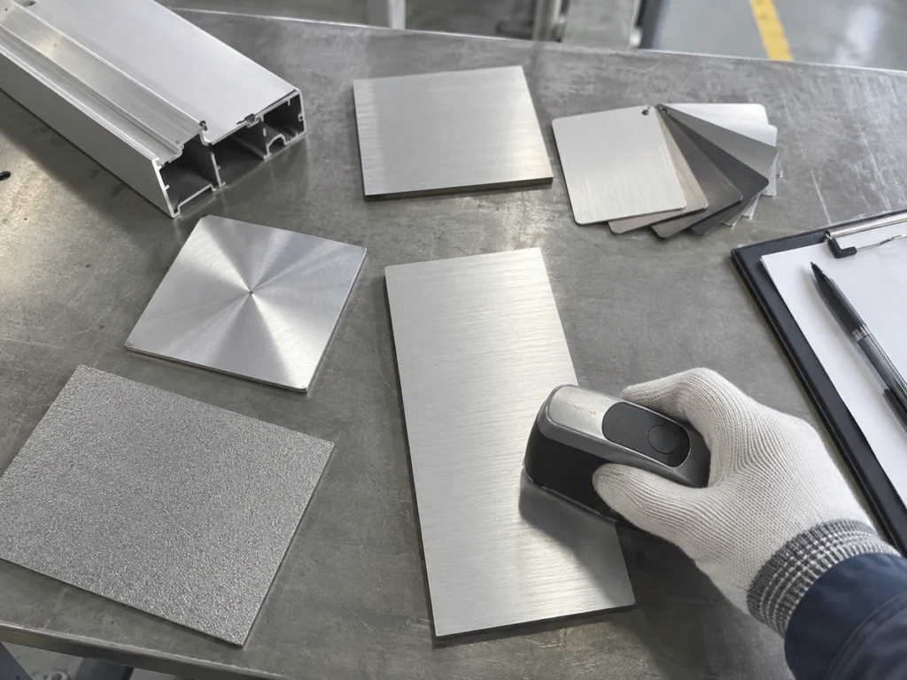
List each layer from one side of the assembly to the other. Identify its material designation, condition, nominal thickness and finish using the released component documents. Show the overlap and joining locations on the drawing.
Keep the layer order explicit when two sides have similar names. “Cover above bracket” is more readable than two unattached material entries. Use component references so the description remains understandable when the finished assembly is rotated.
Include any specified intermediate layer in the inquiry. Ask the joining provider to review the complete stack rather than assuming a trial on two uncoated sheets represents an assembly with a different interface.
State which organization owns any proposed change. If the provider suggests another layer order, overlap or joint type, retain it as a proposal until the responsible design review is complete.
Use a representative sample identity
When sending samples, attach the corresponding component and material references. Record differences from the planned production stack, such as a substitute finish or an unfinished sheet edge.
Ask the provider to identify those differences in its trial record. This makes the resulting recommendation easier to assess against the intended delivery without treating an unnamed sample as production approval.
3. Show tool access and the finished interface
TOX states that punches and dies are matched to the materials, sheet thicknesses and joining force for the application. Obtain the joining provider’s proposed arrangement for your drawing rather than copying tooling settings from a different example.
Show neighboring walls, flanges and assembled parts around each joining location. Ask the provider to mark the intended punch and die sides and explain the access needed for its proposed sequence.
Review the component at the planned joining stage. A location accessible before another panel is fitted may have a different access condition afterward. Keep the operation order connected to the provider’s reviewed arrangement.
Also show the surfaces that matter after joining. A mating panel, sliding item or visible face needs its requirement identified on the released drawing. Have the provider show the proposed formed-point geometry relative to that interface.
Do not change an enclosure’s required sealing or service-access arrangement merely to accommodate a convenient joint location. Keep functional changes within the responsible design review.
4. Keep process checks and joint acceptance readable
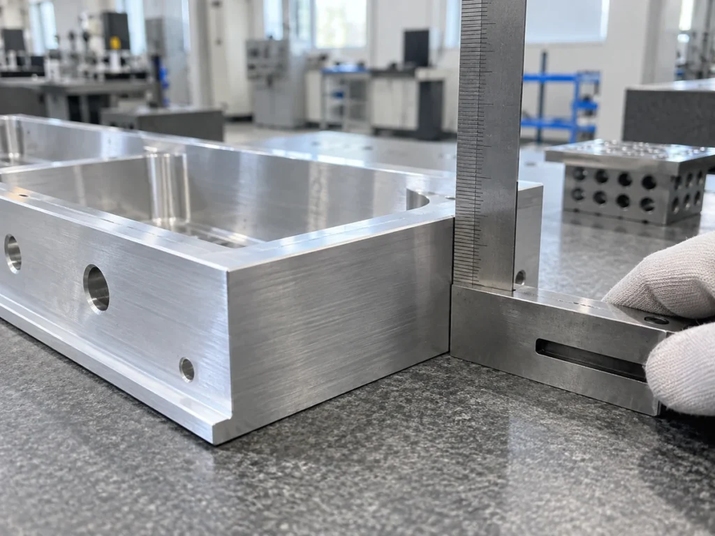
TOX describes residual-bottom-thickness monitoring, section examination and tensile testing among its quality-evaluation approaches. Ask the actual provider which checks are included in its proposed plan and what agreed requirement each addresses.
Request identified results, required units and the applicable acceptance basis. Keep a process-monitoring record under its stated scope; do not turn a single recorded process signal into an unexplained claim about every function of the finished assembly.
If a section is examined, ask for the specimen identity, section location and named reported features. An enlarged image without those references may be difficult to connect to the ordered joining locations.
If the assembly also needs a tightness assessment, identify that requirement separately. Our aluminum leak-testing guide organizes the tested boundary and report. The clinching process name does not supply a leak-test acceptance criterion.
Agree who disposes of an unexpected result and how a retest is recorded. Keep the original observation visible, together with any authorized action and the component stage it represents.
Two fictional proposals for the same cover
Imagine sheet assembly C62, revision B. Offer A includes a joining trial on a supplied stack. Offer B includes production joining and an identified inspection plan. Both use aluminum sheet clinching, but their delivery scopes differ.
For A, ask what recommendation and records the trial will produce, and which sample identity they represent. For B, ask which joining locations, component condition and inspection records are included at delivery.
Compare prices after the scope is clear. Record any remaining tooling, trial or production work as a named item. A trial service and a finished assembly are different deliverables even when they describe the same process.
This invented example provides no joint dimensions, forces or measured results. Its purpose is to make the handover visible in a purchasing comparison.
Carry the joining requirement into part preparation
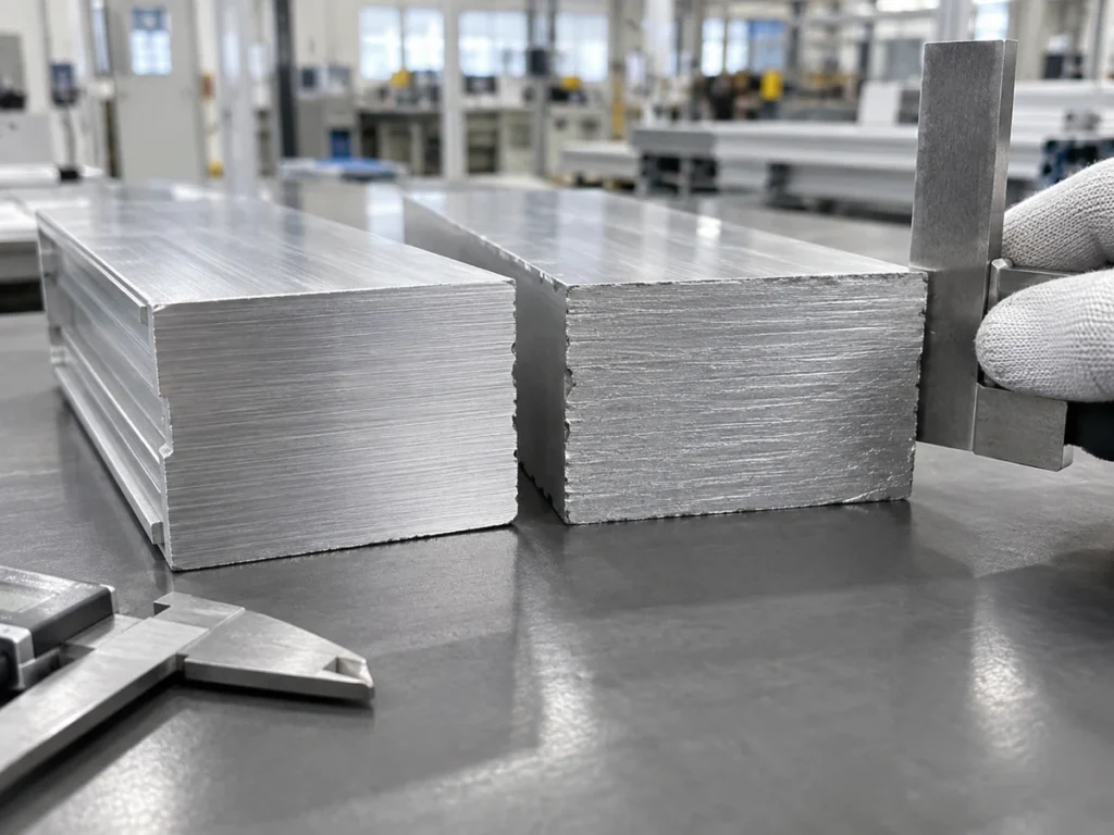
If separate profiles or blanks need cutting, identify their material, cut references, lengths and downstream operations. Keep the joining drawing and any agreed handling instructions with the cutting brief.
Send JiurunCut your aluminum stock drawing and cutting requirements for that preparation scope. Retain clinching-tool selection and joint acceptance with the responsible joining and quality teams.
Questions about aluminum sheet clinching
Does conventional clinching add a rivet?
The process described here forms the sheets into an interlock without adding that fastener. Ask for the actual proposed joint type when the offer uses a broader process label.
Does a visible button prove the internal joint is accepted?
Read the identified inspection evidence against the agreed requirement. The outside appearance alone does not provide the complete acceptance record.
Can I use a sample from another sheet stack?
Identify the differences and have their relevance reviewed. Keep the tested sample and planned production stack distinct in the records.
Is the formed joint a routine removable cover attachment?
State the service requirement before selecting the arrangement. Conventional clinching is described as a permanent sheet connection; a cover that must open needs its own approved attachment design.