
Aluminum H channel cutting begins with a panel joint, not a saw setting. A one-piece H joiner takes a panel edge in each of two opposing pockets. If the two panels differ in thickness, finish, insertion depth or installation order, a cut piece can meet a length tolerance yet fail at the seam. The buyer should release the joint interface and the blank specification separately before requesting a cutting quote.
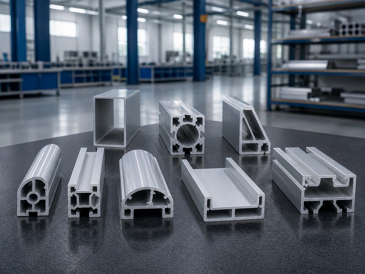
Image note: the featured photograph shows related aluminum extrusion sections. It is illustrative; it is not the H joiner, a project sample, a Jiurun machine configuration or evidence of cutting performance.
Aluminum H channel cutting starts with the joint system
“H channel” can mean a simple one-piece panel joiner or a member in a multi-part trim system. Orange Aluminum describes H channels as panel joiners with two opposing channels. A Metl-Span extrusion guide lists distinct male and female vertical H-joint members and identifies exposed surfaces on its drawings. Canalta Panels also lists an H connector among panel-system extrusions. These are examples of different products, not interchangeable drawings for a Jiurun saw trial.
Ask the system owner for the released part number and cross-section revision. Mark which face is visible, which edge is left and which is right in the installed orientation. If it is a two-part H joint, identify every mating member and specify whether the quotation covers one member, a pair, or a complete installation kit. A saw shop should not infer the section from a small front-view sketch or a nominal channel width.
This is a different buying decision from a U-channel fitted to one panel edge. The H joiner controls the relationship of two panel edges and a visible seam, so both sides must be released together.
Approve both pockets with the actual panel stackups
The drawing should call out the controlling dimensions and tolerances for pocket A and pocket B separately. Record the substrate, coating, film, laminate, gasket or other layer included in the finished panel thickness. State the intended insertion depth on each side and the acceptable fit condition at assembly. A nominal “fits 6 mm panel” note may not explain whether the value refers to raw substrate, finished panel, a gasketed assembly or a particular supplier’s profile.
If the two panel edges are different, do not silently mirror one pocket dimension into the other. If they are intended to be identical, say so on the released drawing and verify both sides on a representative profile sample. Also identify any lip, return, central web or visible reveal that affects the appearance of the seam. These are interface requirements; the saw cannot correct an extrusion that was purchased with the wrong pocket geometry.
A practical fit approval uses two pieces of the actual panel build, with the intended finishes and protective layers, inserted in the specified sequence. Record whether the joint is dry-fit, uses a gasket, needs fasteners, or is retained by another system part. The joint designer owns these choices. A saw trial can show how a particular profile cuts; it cannot certify panel retention, weather sealing or structural performance.
Locate the seam and define each end termination
For a vertical joint, the length datum may run between a sill and a head member, or between another pair of project-defined stops. For a horizontal joint, it may terminate at jambs, corners or neighbouring trims. Give the saw shop the final blank length from a named datum to a named end, plus the drawing revision that establishes any clearance. Do not make the operator calculate a “standard allowance” from the panel height or width: allowances depend on the actual system and installation sequence.
Mark whether the ends are square, mitered, notched or left long for site fitting. If one end meets a corner member and the other remains visible, the two ends may have different acceptance criteria. An H section may be cut to a simple blank while drilling, end caps, deburring, coating repair and installation remain separate downstream operations. State which party performs each operation and whether the quote is for stock lengths, factory cut blanks or finished joiner kits.
Assembly order matters. Can both panels slide into the joiner after the adjacent trims are installed? Does one panel enter first, or must the joiner slide over two panel edges before the frame closes? If the sequence is uncertain, approve a short mock-up before releasing the full cut list. This can reveal an inaccessible insertion route even when every individual dimension looks plausible.
Translate the released joint into a saw setup
Once the section is approved, the cutting supplier can assess the specific extrusion rather than a generic H silhouette. Supply an actual profile sample, a dimensioned cross-section, alloy and temper if known, finish condition, longest and shortest required blanks, batch volume, and the surface that must remain visible. The supplier can then evaluate stock presentation, support, clamp contact, blade path and outfeed handling for that profile.
Thin lips or a projecting flange should not become the only unsupported clamp surface. The setup should hold the profile against a stable reference without closing the pockets or marking the exposed face. This is a setup principle to validate on the sample, not a claim that a particular jig works for every H extrusion. The Jiurun industrial aluminum cutting machine range is a starting point for equipment discussion; model choice and cut quality require the released section and an agreed trial.
Protecting the installed face needs an explicit handling instruction. Define which side may touch the fence, clamp, infeed and packing material, and whether any temporary film remains during cutting. State the acceptable burr and edge appearance on both pocket openings and both visible faces. Avoid specifying only “clean cut,” because one burr may interfere with a panel edge while another is hidden by the installed trim.
Make the first-off test a joint test
Before approving a production batch, inspect a representative first-off cut against the released drawing. Record the measured length and end geometry from the specified datum, inspect both pocket mouths for distortion or burrs, and examine the visible faces for marks. Then test the cut joiner with representative panel edges on both sides. A length-only gauge misses a panel that cannot enter after cutting.
The acceptance record should name the profile and drawing revision, the panel build used for the fit test, the direction of insertion, the sampled cut length, and who approved the result. If a supplier changes the extrusion die, finish thickness, panel supplier, fixture contact or cutting process, decide in advance which changes trigger a new first-off. This protects the joint interface without implying that one successful sample guarantees every future batch.
Separate factory acceptance from site acceptance. A saw-cut blank may pass its length and cut-face checks while the installation still depends on substrate flatness, panel tolerances, fastener positions and the rest of the trim system. Do not attribute an installed seam problem to the saw before checking those interfaces.
Send a quotation package that keeps responsibilities clear
A comparable request for quotation can be short if its attachments are specific:
- Joint release: part number, section revision, one-piece or multi-part system, visible face and installed orientation.
- Two panel interfaces: finished thickness and stackup of panel A and panel B, required insertion depth, gasket or retention details, and approved fit samples.
- Cut list: finished blank lengths, named datums, end types, quantity by length and any paired or handed packing sequence.
- Process boundary: cutting only or additional deburring, drilling, finishing, end caps and kit assembly.
- Acceptance: length and end measurement method, pocket-mouth condition, visible-face protection and two-panel first-off fit check.
- Evidence: cross-section drawing, panel and extrusion samples, and the responsible approver for trial results and drawing changes.
Ask suppliers to mark exceptions rather than silently price a different stock section or substitute a one-sided channel. If the panel system has not released its H joint, the useful next step is a drawing and sample review, not a quote based on the profile letter alone.
What the equipment clip does and does not show
The following video from Jiurun Machinery’s channel shows a general aluminum saw-feeding sequence. It is a related equipment view only. It does not establish this article’s H-section geometry, panel materials, machine model, fixture, cycle time, cut accuracy or approved first-off result.
Request a profile-specific cutting assessment
For a useful response, send Jiurun the released H-joiner section, both panel stackups, the intended assembly sequence, blank lengths and quantity, visible-face requirement, and the acceptance method. Contact JiurunCut to discuss whether a representative cutting trial is appropriate for your profile and to compare equipment and fixture options against the actual joint. A proposal can then state what was tested and what remains the responsibility of the panel-system designer.